Some computer simulations:
ŁŁŁŁŁŁŁŁŁŁŁŁŁŁŁŁŁŁŁŁŁŁŁŁŁŁŁŁŁŁŁŁŁŁŁŁŁŁŁŁŁŁŁŁŁŁŁŁŁŁŁŁŁŁŁŁŁ
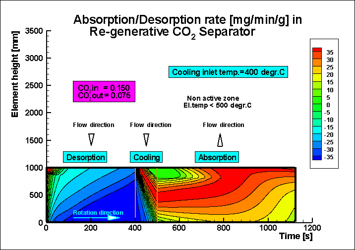
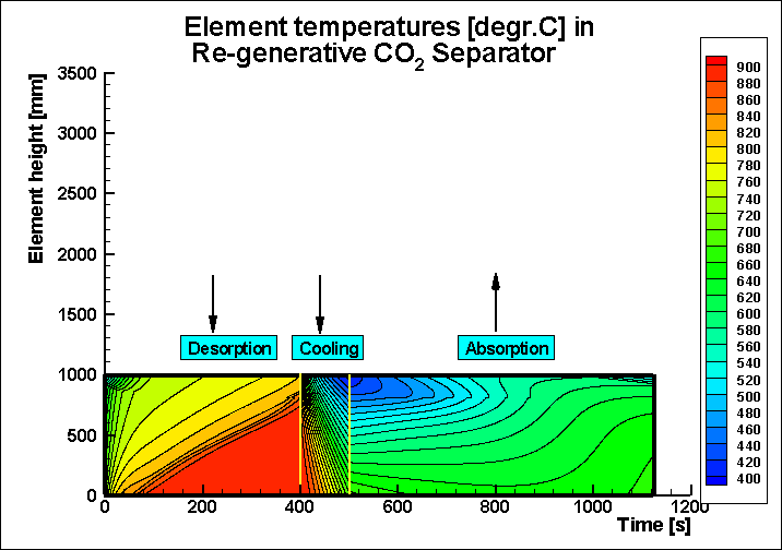
Cleaning of flue Gas from CO2
ŁŁŁŁŁŁŁŁŁŁŁŁŁŁŁŁŁŁŁŁŁŁŁŁŁŁŁŁŁŁŁŁŁŁŁŁŁŁŁŁŁŁŁŁŁŁŁŁŁŁŁŁŁŁŁŁŁ
ALSTOM K.K.,
Japan,
ALSTOM Power Energy Recovery GmbH, Germany:
Kobe University, Kobe, Japan
BoSÕngfors Consulting
Cleaning of Flue Gas from CO2
by the use of lithium silicate (Li4SiO4) coated on
the heat transfer elements in a rotary
heat exchanger.
ŁŁŁŁŁŁŁŁŁŁŁŁŁŁŁŁŁŁŁŁŁŁŁŁŁŁŁŁŁŁŁŁŁŁŁŁŁŁŁŁŁŁŁŁŁŁŁŁŁŁŁŁŁŁŁŁŁ
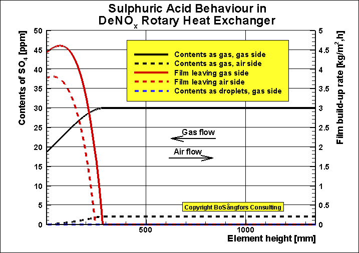
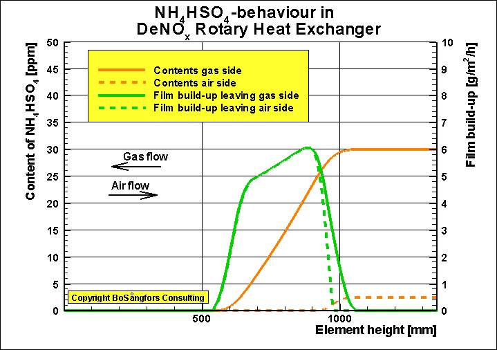
Cleaning of flue Gas from NOx
Calculation of
Temperatures and Film Build-up in a DeNOx Heat Exchanger.

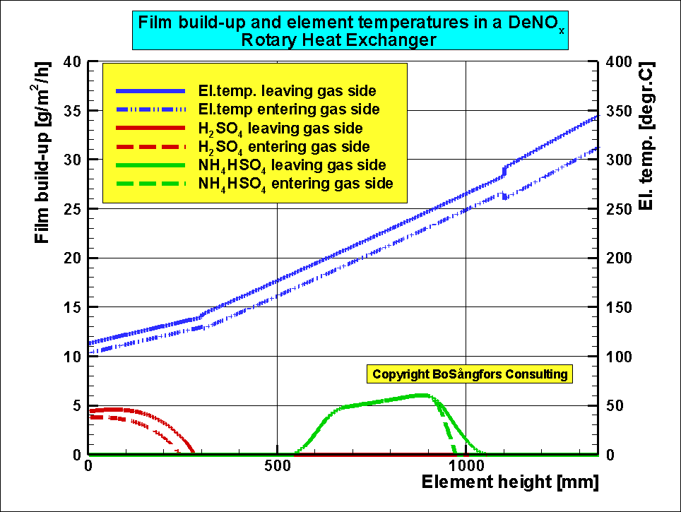
This type of Rotary Heat Exchanger (so called Ljungstr÷m) is operating under equal conditions at Karlshamn Power Station, Karlshamn, Sweden
ŁŁŁŁŁŁŁŁŁŁŁŁŁŁŁŁŁŁŁŁŁŁŁŁŁŁŁŁŁŁŁŁŁŁŁŁŁŁŁŁŁŁŁŁŁŁŁŁŁŁŁŁŁŁŁŁŁŁŁŁŁŁŁŁŁŁŁŁŁŁŁŁŁŁŁŁŁŁŁŁŁŁŁŁŁŁŁŁŁŁŁŁŁŁŁŁŁŁŁŁŁŁŁŁŁŁŁŁŁŁŁŁŁŁŁŁŁŁŁŁŁŁŁŁŁŁŁŁŁŁŁŁŁŁŁŁŁŁŁŁŁŁŁŁŁŁŁ
BoSÕngfors Consulting, Sweden
Leakage analysis of a Bi-sector Rotary Heat Exchanger.
Rotor diameter = 7.48 m
Rotor height = 1.83 m
Rotor speed =
2 rpm
Element
porosity = 0.84
Flue gas flow = 242000 kg/h
Air sector = 180 degree.
Gas sector = 180 degree.
PRESSURES [Pa]
Air in P1= 6325
Air out P2= 5099
Gas in P3=
1216
Gas out P4= 0
CIRCUMFERENTIAL SEAL CLEARANCES [mm]
Air in S1= 2.5
Air out S2= 2.5
Gas in S3= 2.5
Gas out S4= 2.5
TEMPERATURES [degr.C]
Air in T1=40
Air out
T2=502
Gas in T3=601
SECTOR PLATE
CLEARANCES [mm]
Cold end =3
Hot end =3
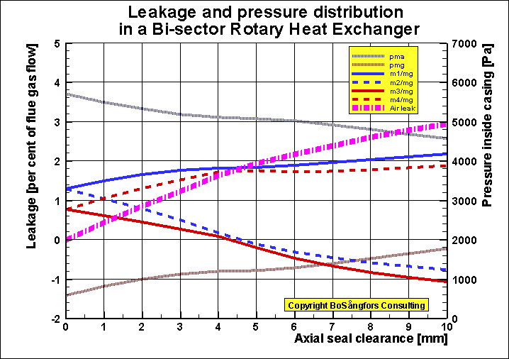
NOMENCLATURE (diagrams)
pma = pressure in volume between
casing and rotor, air side, [Pa]
pmg = pressure in volume between
casing and rotor, gas side, [Pa]
m1 = flow over circumferential seal
inlet air, [kg/h]
m2 = flow over circumferential seal
outlet air, [kg/h]
m3 = flow over circumferential seal
inlet gas, [kg/h]
m4 = flow over circumferential seal
outlet gas, [kg/h]
mg = flue gas flow [kg/h]
Air leak = Air leakage into gas [per cent of flue gas mass flow]
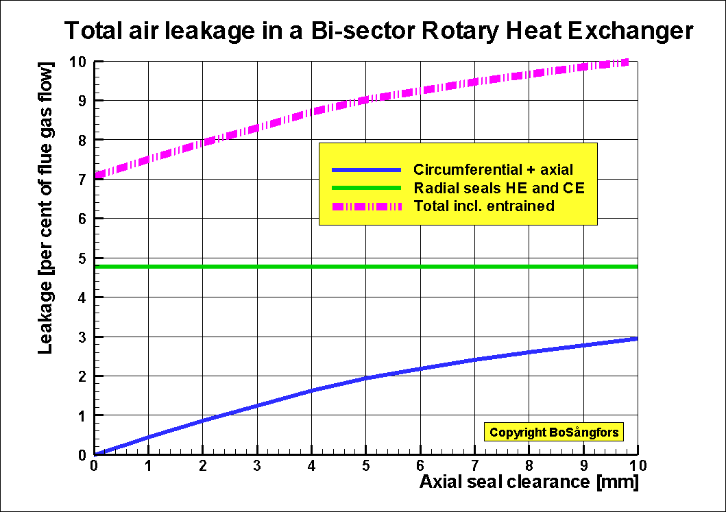
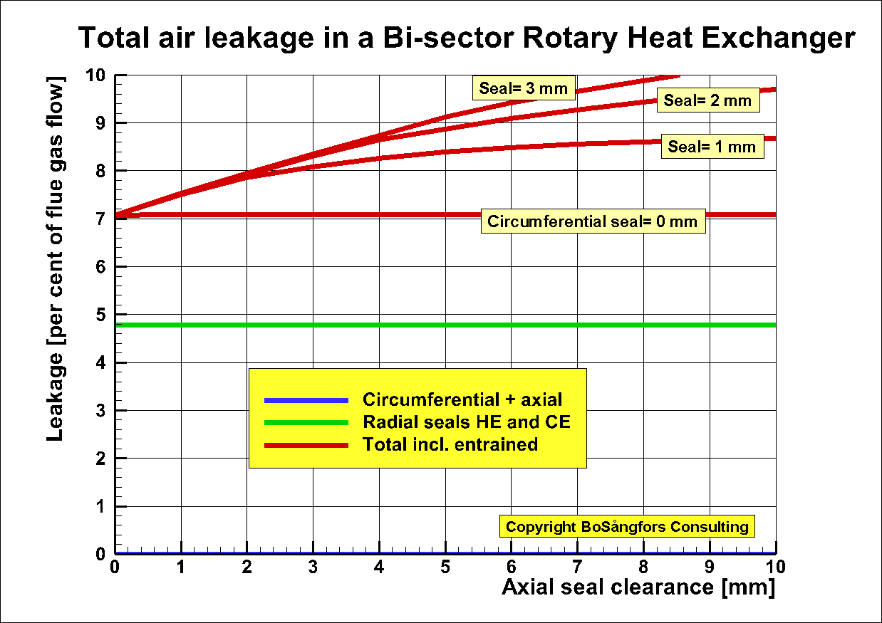
This is a compliment to the above "Leakage analysis of a Bi-sector Rotary Heat Exchanger."
In this are the
CIRCUMFERENTIAL SEAL CLEARANCES [mm]
Air in S1= from 0, 1, 2, to 3
Air out S2= from 0, 1, 2, to 3
Gas in S3= from 0, 1, 2 to 3
Gas out S4= from 0, 1, 2 to 3
Screw Compressors
ŁŁŁŁŁŁŁŁŁŁŁŁŁŁŁŁŁŁŁŁŁŁŁŁŁŁŁŁŁŁŁŁŁŁŁŁŁŁŁŁŁŁŁŁŁŁŁŁŁŁŁŁŁŁŁŁŁ
Effect of oilrate for a high pressure HYDROGEN screw compressor
working with inlet pressure 30 bar and outlet pressure 90 bar
Input data:
Gas=Hydrogen
Pressure in = 30 bar
Pressure out = 90 bar
Temperature gas in = 20.0 centigrade
Temperature injected oil in = 60 centigrade
Built-in volume ratio = 2.19
Rotor diameter = 400 mm
Male rotor tip speed = 79.6 m/s
-------------------------------------------
Calculated results
-----------------------------------------
As can be seen from fig.1 the best adiabatic efficiency is
at oil injection rate 3000 lit/min.
Outlet temperature is at that point 99.8 centigrade
Increase of oil flow increase the outlet flow losses which
increase the power consumption
The mass flow is almost constant above the optimum adiabatic
efficiency point. See fig.2.
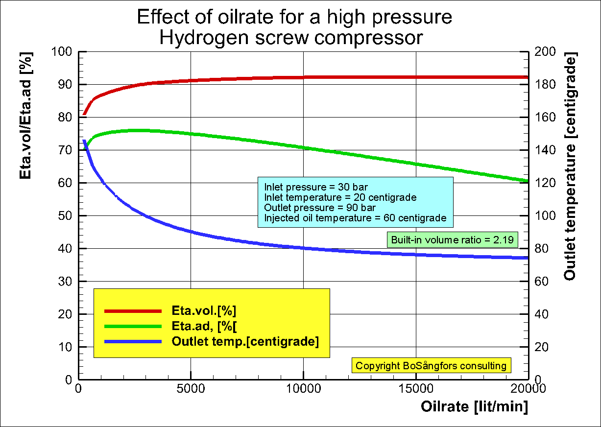
Fig.1
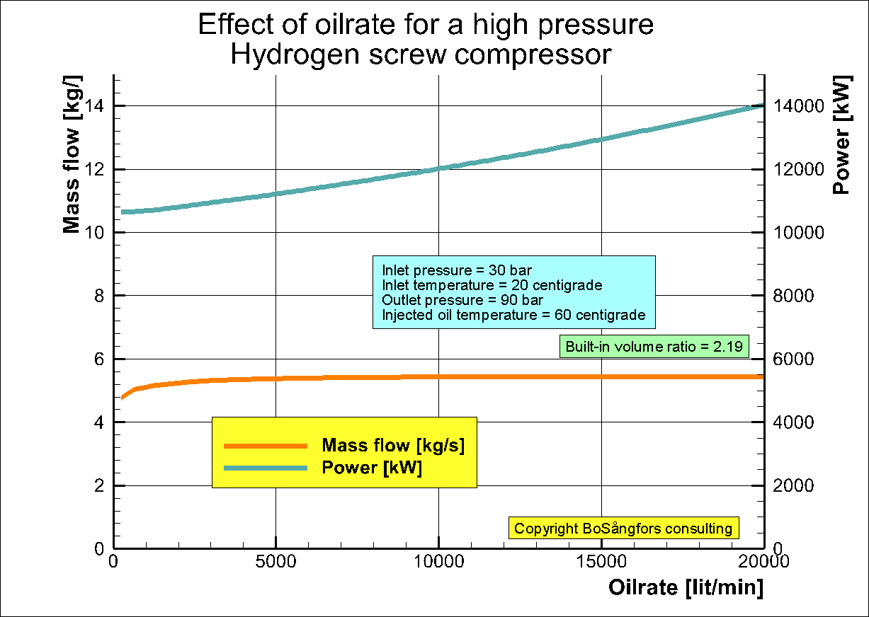
Fig.2
Performance at the optimum
adiabatic efficiency point are presented in fig.3 and 4.
Regarding fig.4 gas quality X is defined as X=(mass of gas)/(mass of gas+mass of oil)
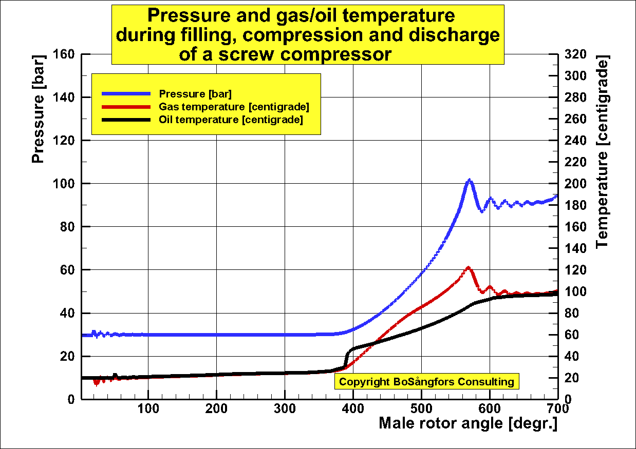
Fig.3
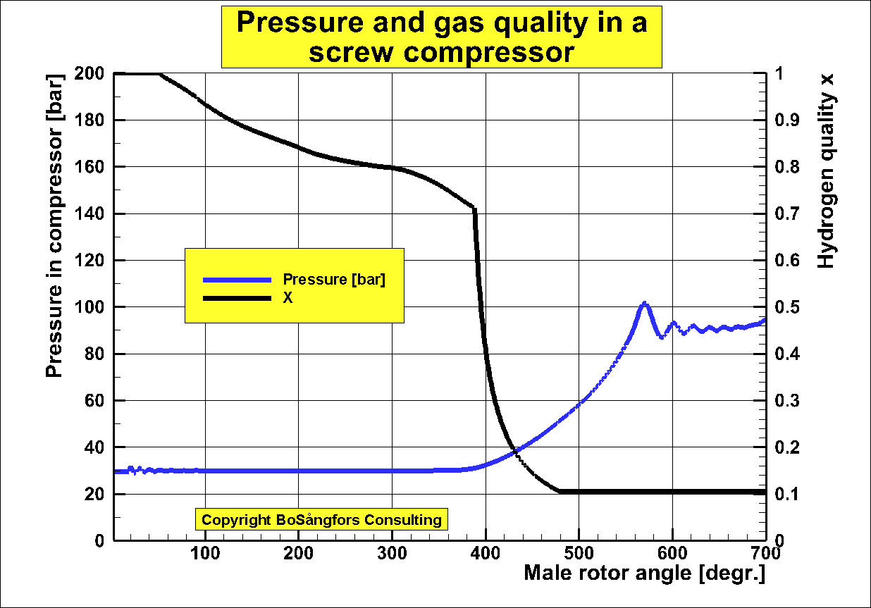
Fig.4
-------------------------------------------
Performance at best adiabatic efficiency -----------------------------------------
Volumetric efficiency = 0.901
Adiabatic efficiency = 0.759
Outlet temperature = 99.8 centigrade
Hydrogen mass flow = 5.317 kg/s
Power consumption = 10940.3 kW
ŁŁŁŁŁŁŁŁŁŁŁŁŁŁŁŁŁŁŁŁŁŁŁŁŁŁŁŁŁŁŁŁŁŁŁŁŁŁŁŁŁŁŁŁŁŁŁŁŁŁŁŁŁŁŁŁŁŁŁŁŁŁŁŁŁŁŁŁŁŁŁŁŁŁŁŁŁŁŁŁŁŁŁŁŁŁŁŁŁŁŁŁŁŁŁŁŁŁŁŁŁŁŁŁŁŁŁŁŁŁŁŁ
1 to 8 bar Hydrogen Water Injected Screw Compressor Performance.Water lubricated rotors.
The calculations are made in accordance with the theory presented in the Purdue paper
Volumetric efficiency = 0.909
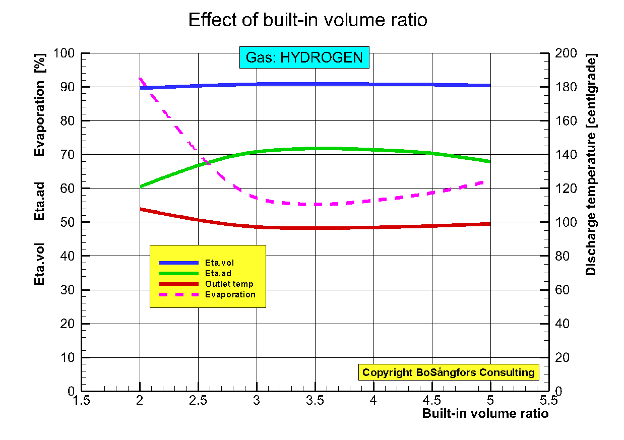
Fig.1
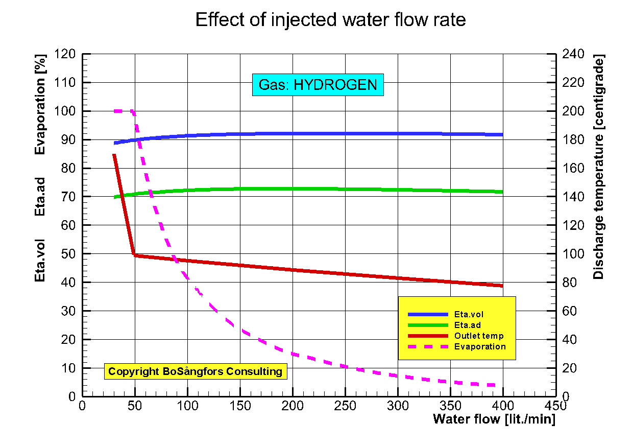
Fig.2
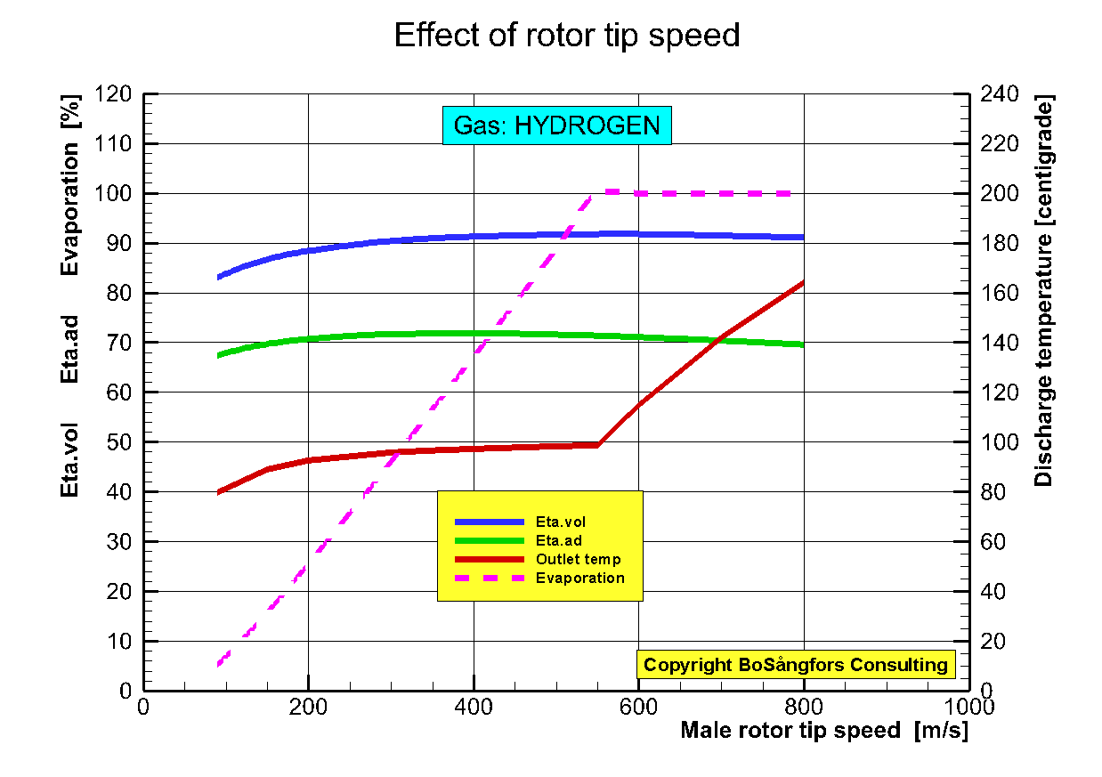
Fig.3
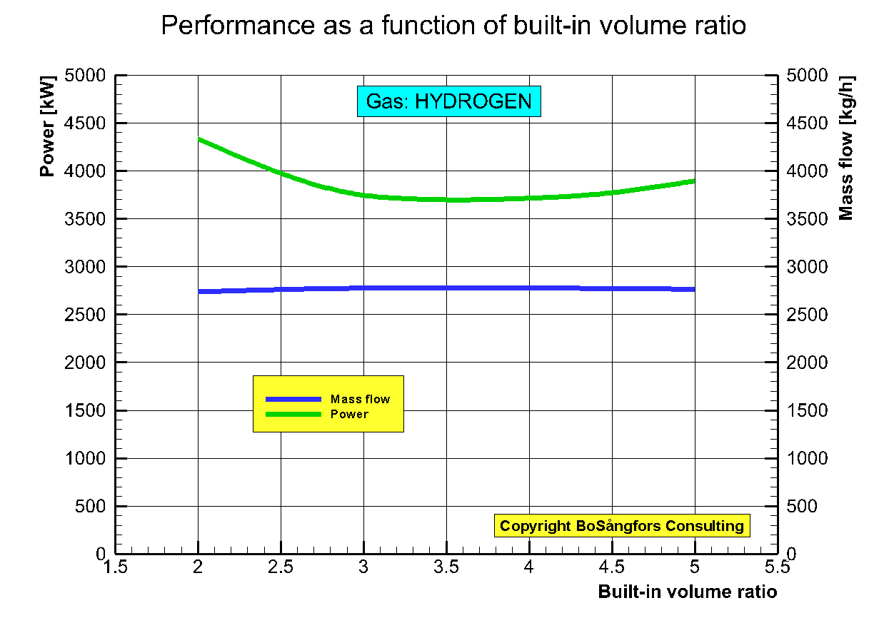
Fig.4
===================================================================================================================
1 to 40 bar Hydrogen
Screw Compressor.
Pressure and gas/oil
temperatures during, filling,
compression and
discharge
Gas=Hydrogen
Built-in volume ratio = 5.0
Rotor diameter = 400 mm
Volumetric efficiency = 0.890
------------------------------------------------------------------------------------------------------------
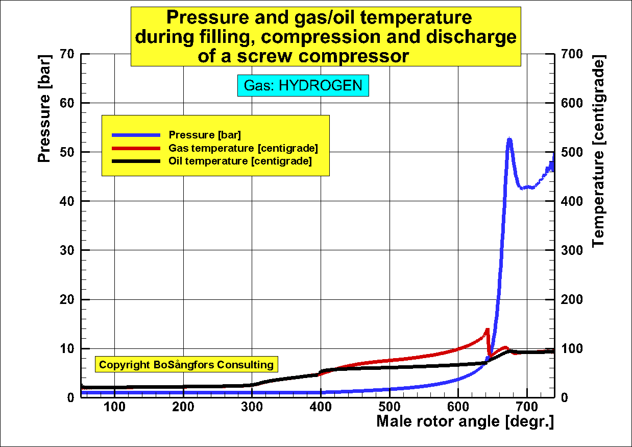
Fig.1
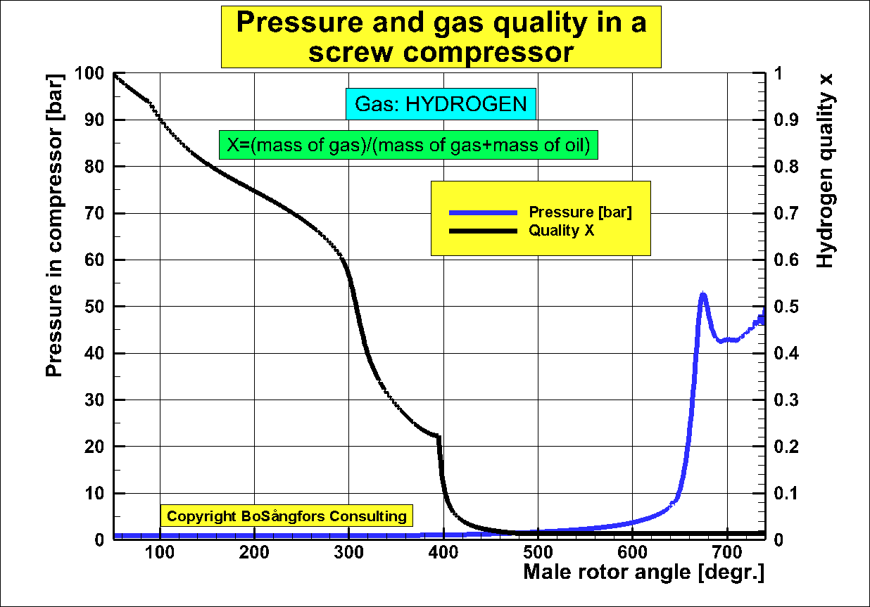
Fig.2
High Pressure Hydrogen
Screw Compressor.
Pressure and gas/oil
temperatures during, filling,
compression and
discharge
Gas=Hydrogen
Built-in volume ratio = 2.19
Rotor diameter = 400 mm
Volumetric efficiency = 0.902
------------------------------------------------------------------------------------------------------------
Fig.1
Fig.2
ŁŁŁŁŁŁŁŁŁŁŁŁŁŁŁŁŁŁŁŁŁŁŁŁŁŁŁŁŁŁŁŁŁŁŁŁŁŁŁŁŁŁŁŁŁŁŁŁŁŁŁŁ
==================================================================================================================================================================
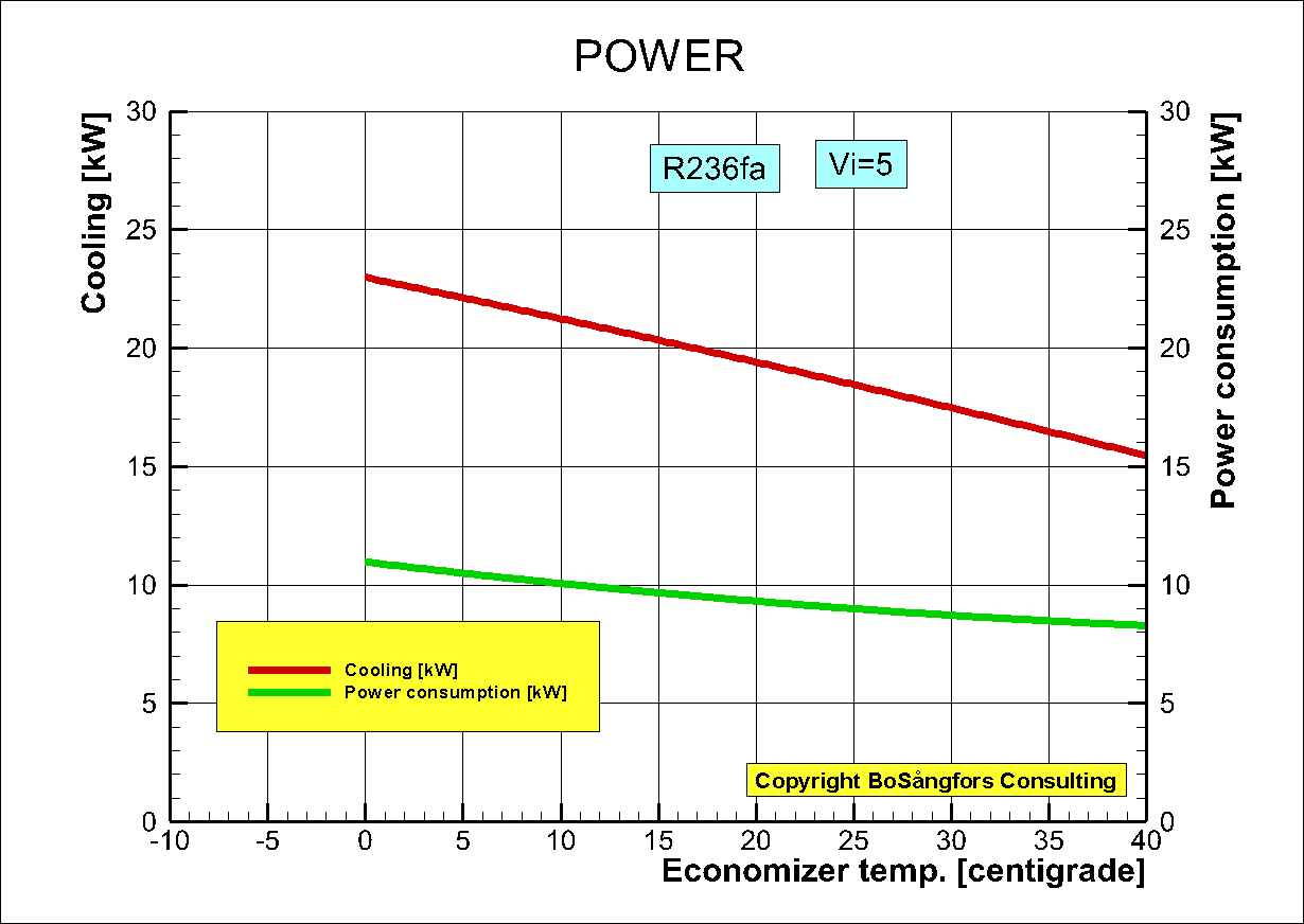
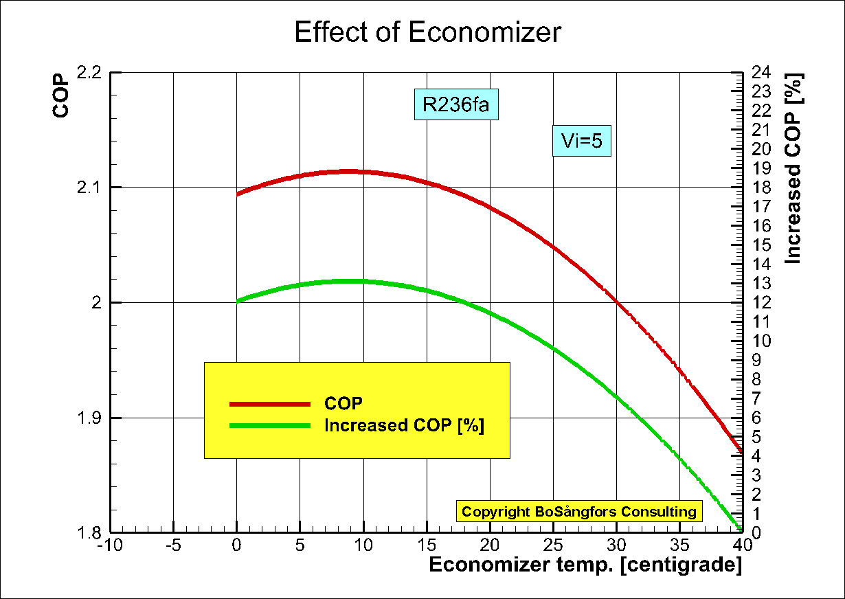
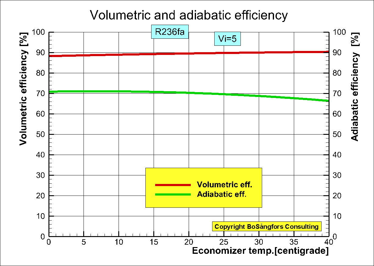
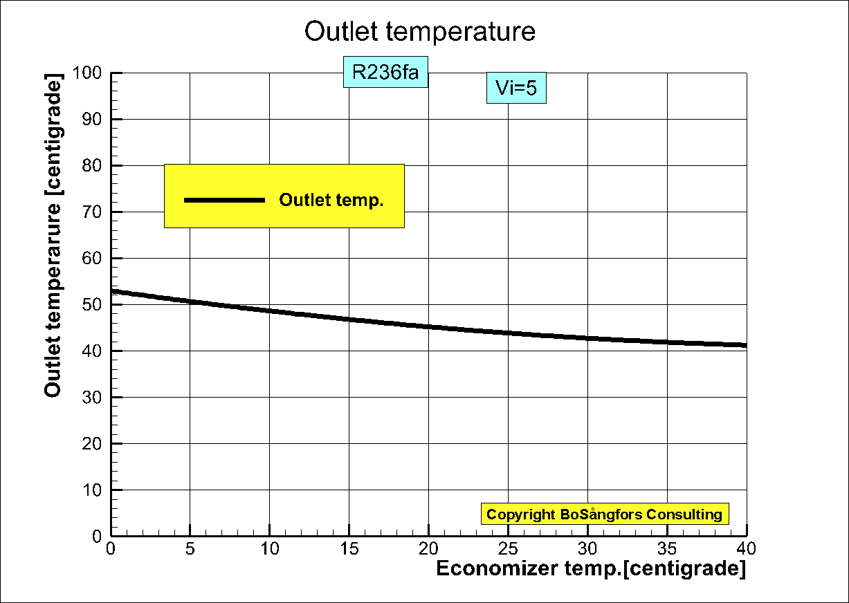
Optimization of Economizer performance for a refrigeration process using a twin
screw compressor
Input Data
Refrigerant = R236fa
Pressure in = 0.43759 bar
Pressure out = 4.3672 bar
Temperature in = -10
centigrade
Temperature injected oil in
= 40 centigrade
Oil rate = 60 lit/min
Built-in volume ratio = 5.0
Rotor diameter = 111 mm
Male rotor tip speed = 25
m/s
Closing of inlet port = 375
degr.
Injection of oil = 395 degr.
Evaporator temperature =-20
centigrade
Condensor temperature = 40
centigrade
Injection
condition
Injection of R236fa from
economizer starts direct
after closing of inlet port,
Stop of injection when
control volume pressure is higher
than economizer pressure.
All calculations have used
REFPROP for all R236fa data,
Conclusions
Fig.3 gives max. increase of COP at economizer temp. = 10 centigrade
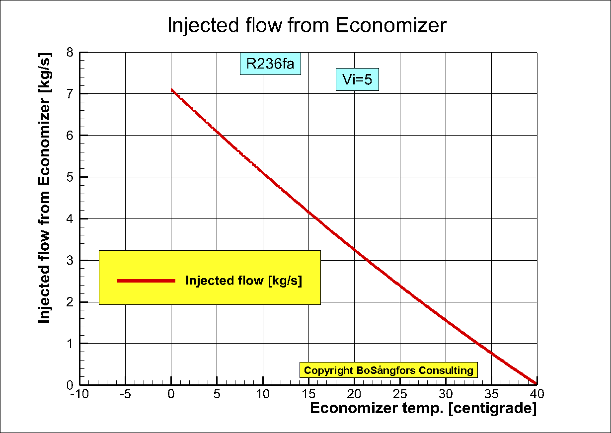
Fig.1
ŁŁŁŁŁŁŁŁŁŁŁŁŁŁŁŁŁŁŁŁŁŁŁŁŁŁŁŁŁŁŁŁŁŁŁŁŁŁŁŁŁŁŁŁŁŁŁŁŁŁŁŁŁŁŁŁŁŁŁŁŁŁŁŁŁŁŁŁŁŁŁŁŁŁŁŁŁŁŁŁŁŁŁŁŁŁŁŁŁŁŁŁŁŁŁŁŁŁŁŁŁŁŁŁŁŁŁŁŁŁŁ
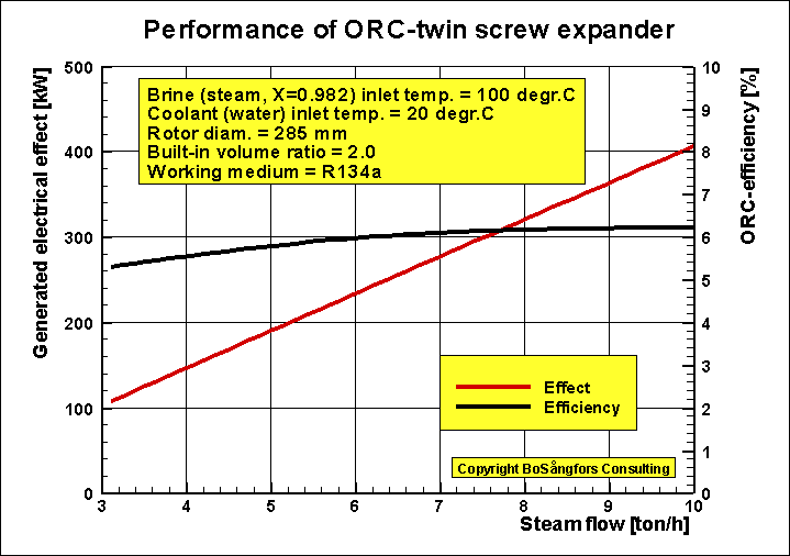
ORC-system using Screw Expanders
ŁŁŁŁŁŁŁŁŁŁŁŁŁŁŁŁŁŁŁŁŁŁŁŁŁŁŁŁŁŁŁŁŁŁŁŁŁŁŁŁŁŁŁŁŁŁŁŁŁŁŁŁŁŁŁŁŁŁŁŁŁŁŁŁŁŁŁŁŁŁŁŁŁŁŁŁŁŁŁŁŁŁŁŁŁŁŁŁŁŁŁŁŁŁŁŁŁŁŁŁŁŁŁŁŁŁŁŁŁŁŁ
GEOTHERMAL
Heat
recovery from low quality steam using twin screw expanders
The intension of this set up of calculations is to show
that it is possible to get reasonable results from a heat
source of low quality
if you expand the steam to a lower pressure.
Hereby you increase the steam quality enough to use the steam as inlet to a
screw expander.
Stage 2: ORC using R134a Screw Expander, Diam. = 948 mm, Inlet x=1.0
Fig.1 shows the total generated effect as a function of the brine flow in the
system.
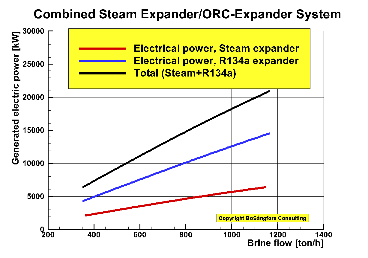
Fig.1
Stage
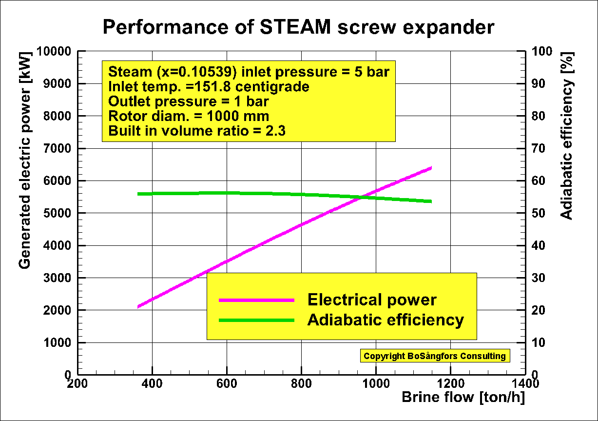
1: Steam Screw Expander in above Combined System
NOTE: Since this steam expander operates with low steam quality (x=0.10359 at inlet) water lubricated rotors might be used instead of synchronizing gears.
Fig.2 shows that the generated effect and the adiabatic efficiency as a function of the brine (steam) flow
leaving the steam expander.
Stage 2: ORC using Screw Expander
in above Combined System
Coolant = Water
Coolant temp in = 20 centigrade
Evaporation temp = 85 centigrade
Condensing temp = 30 centigrade
Condensing pressure = 7.702 bar
Temp. efficiency (Evaporator +Preheater) = 90 %
Temp. efficiency Condenser = 90 %
High
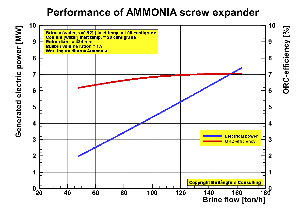
performance 2 stage system using twin screw expanders
Stage 1: Steam Screw Expander, Diam.
= 1000 mm
Stage 2: ORC using Ammonia Screw
Expander, Diam. = 484 mm
Tip speeds:
Steam expander 40 to 150 m/s
Ammonia: ORC-expander 20 to 75 m/s
Fig.1 shows the total generated effect as a function of the brine flow in the system.
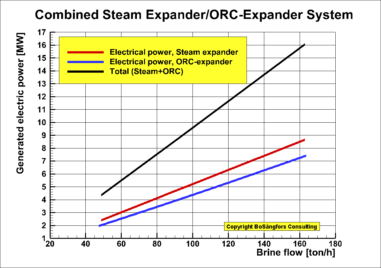
Fig.1.
Stage 1: Steam Screw Expander in
above Combined System
Rotor diameter = 1000 mm
Built-in volume ratio = 2.0
Inlet/Outlet pressure = 5/1 bar,
Inlet/Outlet temperature 151.8/100.0 centigrade
Male rotor tip speed = 40 < Vtip < 150 m/s
Generator efficiency = 0.95
Fig.2 shows that the generated effect and the adiabatic efficiency as a function of the brine (steam) flow leaving the steam expander.
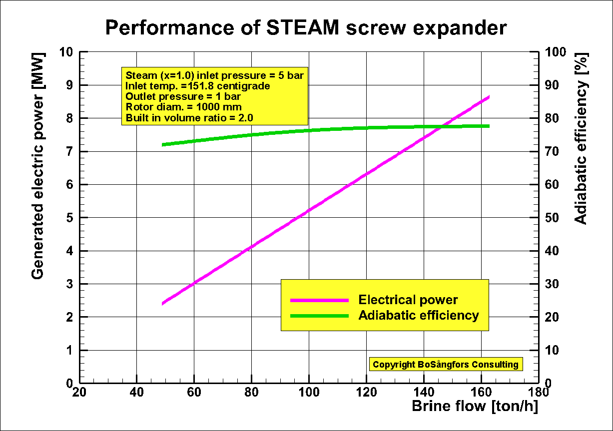
Fig. 2
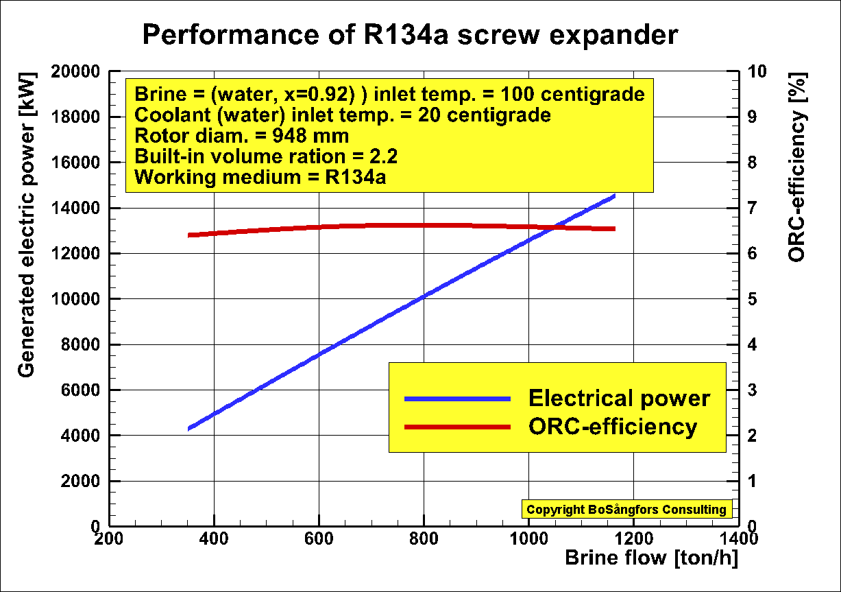
Stage 2: ORC using Screw Expander in
above Combined System
Rotor diameter = 484 mm
Built-in volume ratio = 1.9
Male rotor tip speed = 20 < Vtip < 75 m/s
Brine = Steam of temperature 100
centigrade leaving the steam expander
stage 1
Coolant = Water
Brine temp in = 100
centigrade.
Quality x = 0.92
Coolant temp in = 20 centigrade
Working medium = Ammonia
Ammonia quality x at expander inlet = 1.0
Evaporation temp = 85 centigrade
Condensing temp = 35 centigrade
Temp. efficiency (Evaporator +Preheater) = 90 %
Temp. efficiency Condenser = 90 %
Generator efficiency = 0.95
Pump losses in ORC system are included.
Brine pump losses are not included.
Coolant pump losses are included.
Fig 3 shows generated power and ORC-efficiency.
ŁŁŁŁŁŁŁŁŁŁŁŁŁŁŁŁŁŁŁŁŁŁŁŁŁŁŁŁŁŁŁŁŁŁŁŁŁŁŁŁŁŁŁŁŁŁŁŁŁŁŁŁŁŁŁŁŁŁŁŁŁŁŁŁŁŁŁŁŁŁŁŁŁŁŁŁŁŁŁŁŁŁŁŁŁŁŁŁŁŁŁŁŁŁŁŁŁŁŁŁŁŁŁŁŁŁŁŁŁŁŁŁ
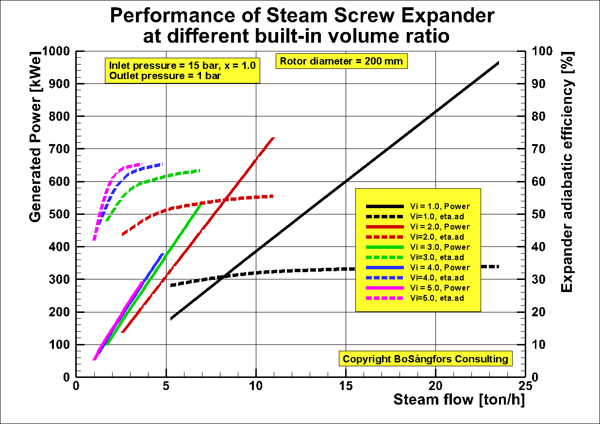
Performance of Steam Screw Expander at different built-in volume
ratio
This graph shows
how the different built-in volume ratio effects the generated
electric power and the screw expander adiabatic efficiency.
Generator
efficiency = 0.95
The rotor tip
speeds are from 20 m/s up to 110 m/s.
As can be seen
low built-in volume ratio leads to high power output but to low
adiabatic efficiency.
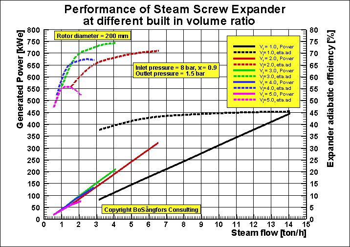
The graph below is for inlet pressure 8 bar and outlet pressure 1.5 bar.
Note: The steam quality x=0.90
Generator efficiency = 0.95
As can be seen in this example there is a built-in volume ratio point that gives the best adiabatic efficiency.
Another point of
interest is that Vi=3.0 and Vi=4.0 are quite close in
performance.
ŁŁŁŁŁŁŁŁŁŁŁŁŁŁŁŁŁŁŁŁŁŁŁŁŁŁŁŁŁŁŁŁŁŁŁŁŁŁŁŁŁŁŁŁŁŁŁŁŁŁŁŁŁŁŁŁŁŁŁŁŁŁŁŁŁŁŁŁŁŁŁŁŁŁŁŁŁŁŁŁŁŁŁŁŁŁŁŁŁŁŁŁŁŁŁŁŁŁŁŁŁŁŁŁŁŁŁŁŁŁŁ
Effect of different steam quality X upon the
performance of a SteamTwin Screw Expander driving a generator producing
electrical power.
Male
rotor diameter = 285 mm.
Outlet pressure = 2.7 bar
The presented data set shows the generated electrical power as a function of the
steam flow at various steam quality x.
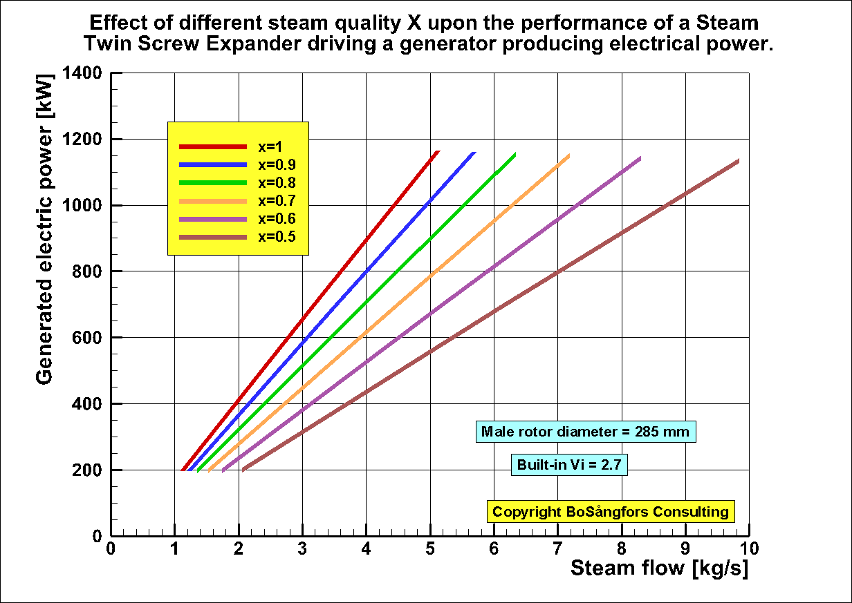
Generated electrical power as a function of steam flow.
ŁŁŁŁŁŁŁŁŁŁŁŁŁŁŁŁŁŁŁŁŁŁŁŁŁŁŁŁŁŁŁŁŁŁŁŁŁŁŁŁŁŁŁŁŁŁŁŁŁŁŁŁŁŁŁŁŁŁŁŁŁŁŁŁŁŁŁŁŁŁŁŁŁŁŁŁŁŁŁŁŁŁŁŁŁŁŁŁŁŁŁŁŁŁŁŁŁŁŁŁŁŁŁŁŁŁŁŁŁŁŁŁ
Effect of superheated
steam upon the performance of a Steam
Twin Screw Expander driving a generator
producing electrical power.
Male
rotor diameter = 285 mm.
Outlet pressure = 2.7 bar
The presented data set shows the generated electrical power as a function of the
steam flow at various steam superheat.
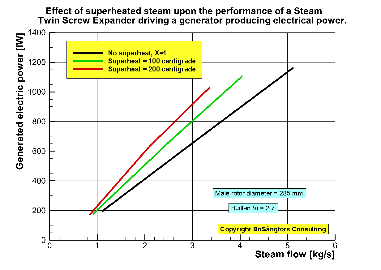
Generated electrical power as a function of steam flow.
ŁŁŁŁŁŁŁŁŁŁŁŁŁŁŁŁŁŁŁŁŁŁŁŁŁŁŁŁŁŁŁŁŁŁŁŁŁŁŁŁŁŁŁŁŁŁŁŁŁŁŁŁŁŁŁŁŁŁŁŁŁŁŁŁŁŁŁŁŁŁŁŁŁŁŁŁŁŁŁŁŁŁŁŁŁŁŁŁŁŁŁŁŁŁŁŁŁŁŁŁŁŁŁŁŁŁŁŁŁŁŁŁ
As can be seen it is very important to have a good steam quality. I.e. = 1.
Therefore slight superheating is recommended.
For instance if X=0.5 instead of 1, the steam consumption will increase with a factor 2. I.e.the machine acts as if 50% of the flow is by-passed.
ŁŁŁŁŁŁŁŁŁŁŁŁŁŁŁŁŁŁŁŁŁŁŁŁŁŁŁŁŁŁŁŁŁŁŁŁŁŁŁŁŁŁŁŁŁŁŁŁŁŁŁŁŁŁŁŁŁŁŁŁŁŁŁŁŁŁŁŁŁŁŁŁŁŁŁŁŁŁŁŁŁŁŁŁŁŁŁŁŁŁŁŁŁŁŁŁŁŁŁŁŁŁŁŁŁŁŁŁŁŁŁŁŁŁŁŁŁŁŁŁŁŁŁŁŁŁŁŁŁŁŁŁŁŁŁŁŁŁŁŁŁ
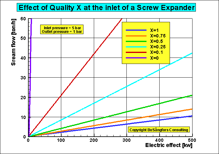
Effect of inlet steam
quality X if the inlet steam mass flow is constant.
This is an
addition to the data file ōImportance of having good steam quality x at the
inlet of a Steam Screw Expander generating electric powerö earlier uploaded on
Research Gate
In these calculations
the steam mass flow is kept constant by changing the inlet pressure and
temperature. As can be seen the generated power as well as the inlet pressure
decreases with decreasing inlet steam quality.
Other
data are:
Rotor
diameter = 200 mm
Inlet/Outlet pressure = 8/1 bar at steam quality = 1.0
Inlet/Outlet temperature 170.4/99.6 centigrade at steam quality = 1.0
Inlet steam mass flow = 7.2 ton/h in all
calculations.
Built in volume ratio =1.0.
By
having this value effects from flashing or condensation are outside the control
volume. I.e. they can be neglected
Male rotor tip speed = 60 m/s
Generator efficiency = 0.95
Fig.1 shows that the generated effect decreases with decreasing steam quality.
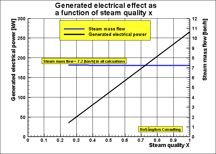
Fig. 1
This is
due to the decrease in inlet pressure, See fig.2.
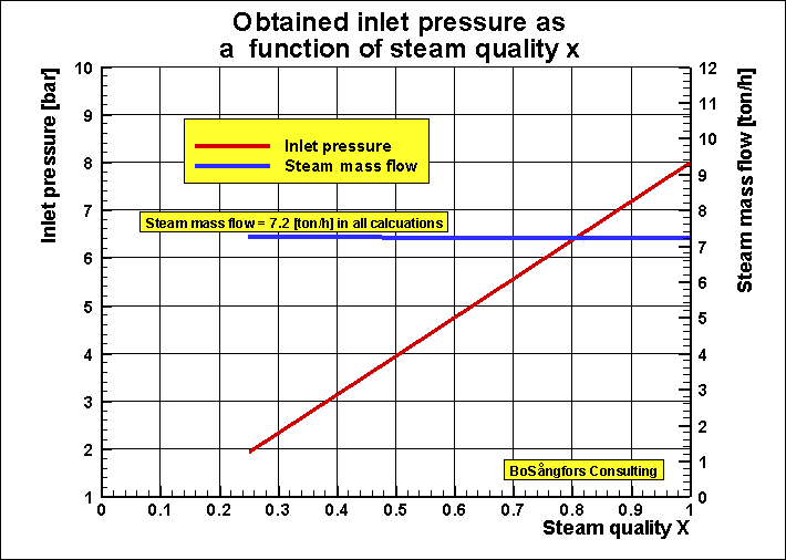
Fig. 2
Fig. 3
shows the decrease of inlet pressure and generated electric power.
As is
obvious from these calculations the inlet quality is an important parameter,
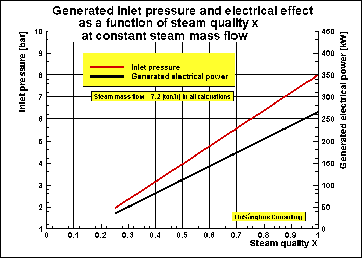
Fig. 3
ŁŁŁŁŁŁŁŁŁŁŁŁŁŁŁŁŁŁŁ-------------------------------------------------------------------ŁŁŁŁŁŁŁŁŁŁŁŁŁŁŁŁŁŁŁŁŁŁŁŁŁŁŁŁŁŁŁŁŁŁŁŁŁŁŁŁŁŁŁŁŁŁŁŁŁŁŁŁŁŁŁŁŁŁŁŁŁŁŁŁŁŁŁŁŁŁŁŁŁŁŁŁŁŁŁŁŁŁŁŁŁŁŁŁŁŁŁŁŁŁŁŁŁŁŁŁŁŁŁŁŁŁŁŁŁŁŁŁŁŁŁŁŁŁŁŁ
Importance of having good steam quality x at the inlet of a Steam Screw Expander generating electric power.
The water volume is very small.
------------------
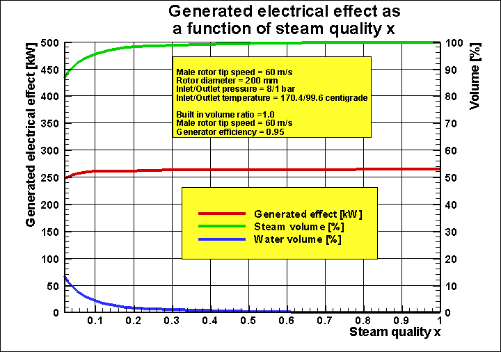
Fig. 1
This looks very nice, but a look at fig.2 below shows that the steam consumption
is very dependent of the steam quality x.
For example if you decrease the steam quality from 1 to 0.5 the steam mass flow
increases twice.
ŁŁŁŁŁŁŁŁŁŁŁŁŁŁŁŁŁŁŁ-------------------------------------------------------------------ŁŁŁŁŁŁŁŁŁŁŁŁŁŁŁŁŁŁŁŁŁŁŁŁŁŁŁŁŁŁŁŁŁŁŁŁŁŁŁŁŁŁŁŁŁŁŁŁŁŁŁŁŁŁŁŁŁŁŁŁŁŁŁŁŁŁŁŁŁŁŁŁŁŁŁŁŁŁŁŁŁŁŁŁŁŁŁŁŁŁŁŁŁŁŁŁŁŁŁŁŁŁŁŁŁŁŁŁŁŁŁŁŁŁŁŁŁŁŁŁ
Effect of built-in
volume ratio at different steam quality X upon the performance
of aTwin Screw Steam Expander driving a
generator producing electrical power.
In order to give more information about the effects of various built-in
ratio at different steam quality X, when using a screw expander for
generating electrical power these calculations are presented.
The expander is a dry twin screw expander with synchronizing bearings
Profile = 4+6-combination
Male rotor diameter = 285 mm
Female rotor diameter = 285 mm.
Male rotor tip velocity = 60 m/s
Inlet pressure = 5 bar.
Inlet temperature = 151.85
centigrade
Outlet pressure = 1bar
The quality x noted in the graphs are values at the screw expander inlet.
Generator efficiency = 95 %
Calculation
results:
The presented data sets below show the following:
Fig.1 shows the generated electrical power as a function of built-in
volume ratio at various steam quality X.
Fig.2 shows the mass flow through the expander.
Fig.3 shows the generated specific power.
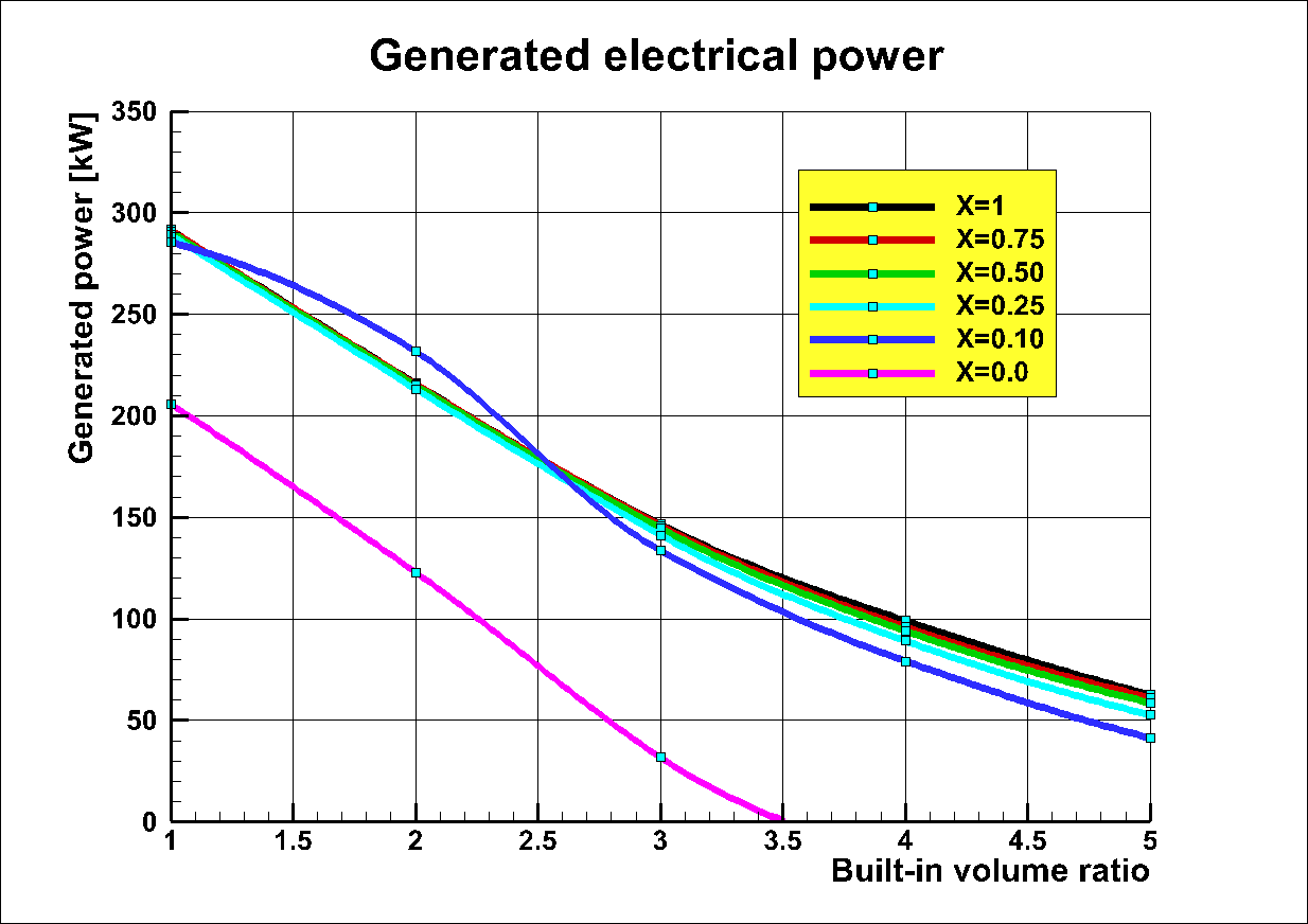
Fig. 1. Generated electrical power as a function of built-in volume ratio.
As can be seen the generated power is
about the same for quality 0.10 < x < 1.
Notice that at x=0.0 the generated power
is drastically decreased due to high inlet
pressure drop caused by the water quality x=0.
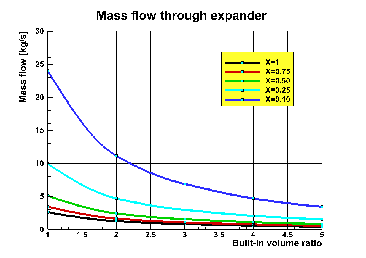
Fig. 2. Mass flow through
expander as a function of built-in volume ratio.
As is obvious the mass flow through the screw expander increases with decreasing quality x.
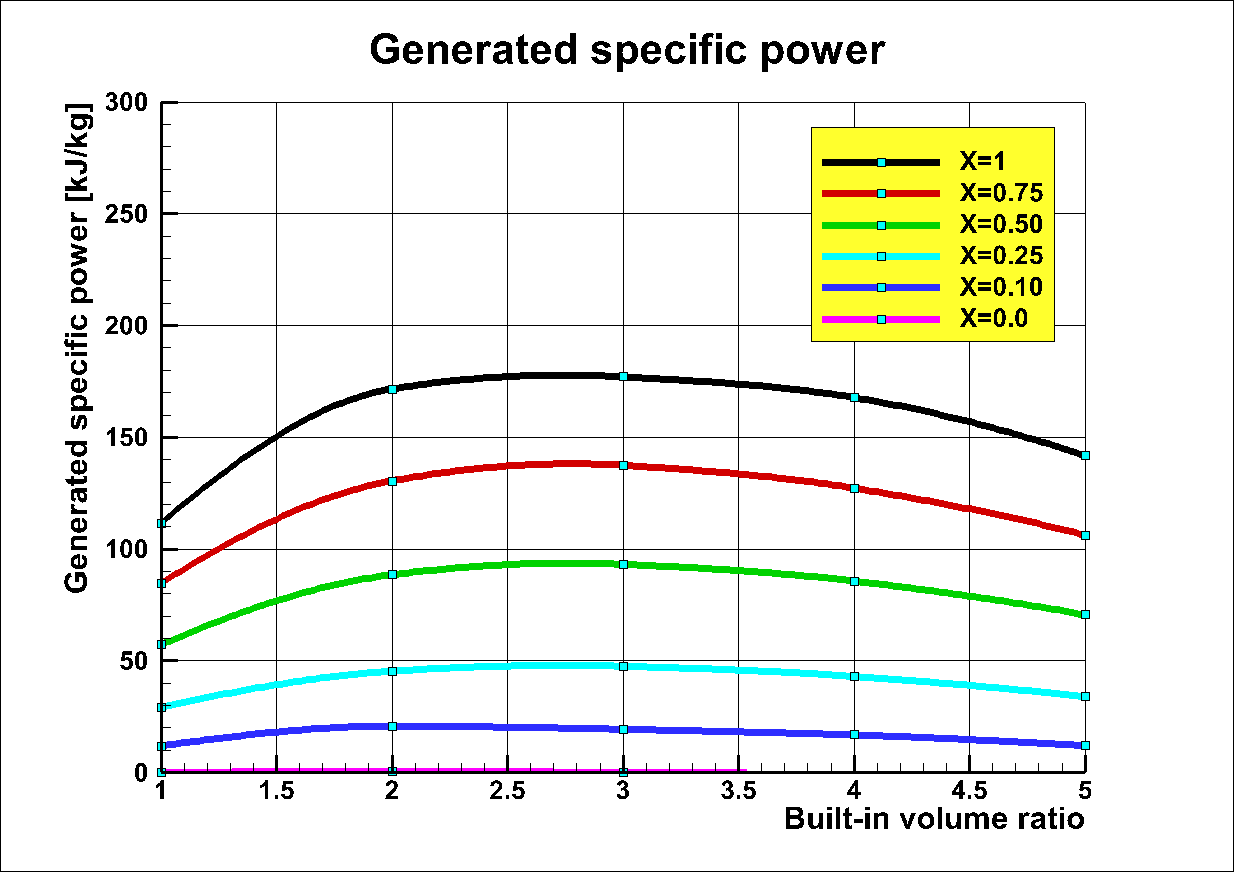
Fig. 3. Generated
specific power as a function of built-in volume ratio.
The generated specific power is
calculated: (generated power [kW])/ (mass flow through expander [kg/s]).
Conclusion
It is quite obvious that it is important to have a high quality x.
ŁŁŁŁŁŁŁŁŁŁŁŁŁŁŁŁŁŁŁŁŁŁŁŁŁŁŁŁŁŁŁŁŁŁŁŁŁŁŁŁŁŁŁŁŁŁŁŁŁŁŁŁŁŁŁŁŁŁŁŁŁŁŁŁŁŁŁŁŁŁŁŁŁŁŁŁŁŁŁŁŁŁŁŁŁŁŁŁŁŁŁŁŁŁŁŁŁŁŁŁŁŁŁŁŁŁŁŁŁŁŁŁ
ORC-system
Shaft Power and Generated Electric Power
from a Screw Expander operating in an
ORC-system using different working media
In order to give some feeling about the effects of different working media on the performance of a twin screw expander with the diameter 285 mm these calculations are presented.
As is shown the choice of working media is very important and determines the size of the screw expander.--------
The expander is a dry screw expander with synchronizing bearings.Rotor diameter = 285 mm
Brine = Water
Coolant = Water
Brine temp = 100 centigrade
All calculations are at built-in volume ratio = 2.0 and male rotor tip speed = 60.0 m/s
Coolant pump losses are included.
Temperature efficiency Condenser = 90 %
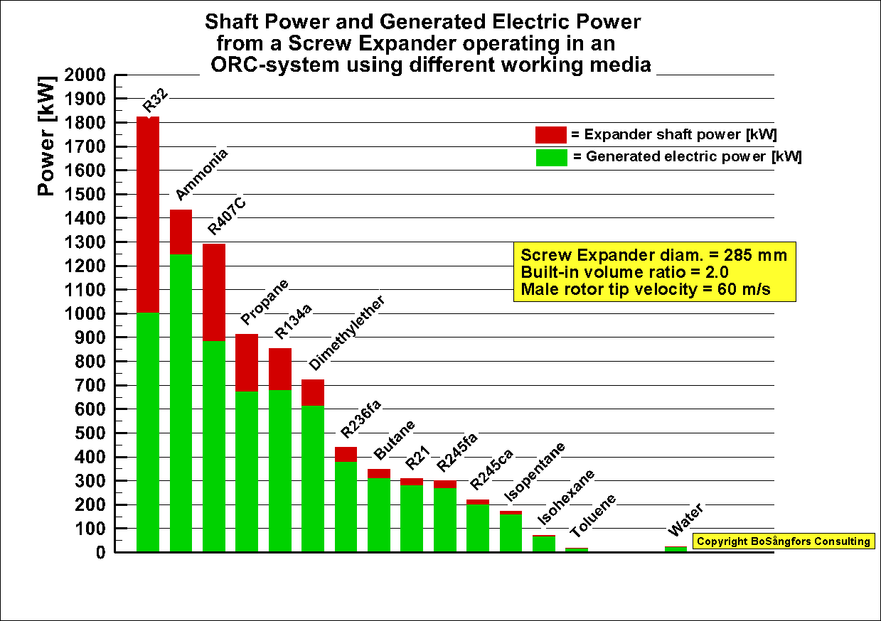
The main reason for this is that the media pumping power is higher for R32 than for Ammonia.
ŁŁŁŁŁŁŁŁŁŁŁŁŁŁŁŁŁŁŁŁŁŁŁŁŁŁŁŁŁŁŁŁŁŁŁŁŁŁŁŁŁŁŁŁŁŁŁŁŁŁŁŁŁŁŁŁŁŁŁŁŁŁŁŁŁŁŁŁŁŁŁŁŁŁŁŁŁŁŁŁŁŁŁŁŁŁŁŁŁŁŁŁŁŁŁŁŁŁŁŁŁŁŁŁŁŁŁŁŁŁŁŁŁŁŁŁŁŁŁŁŁŁŁŁŁŁŁŁŁŁŁŁŁŁŁŁŁŁŁ
Effect of different built-in volume ratio
upon the performance of an ORC-system,
which uses a helical screw expander for
driving a generator producing electrical power.
In order to give more information about the effects of
various built-in volume ratio Vi, when using a screw expander in an
ORC-system these calculations are presented.
The
presented graph presents the performance as a function of the brine flow.
The expander
is a dry screw expander with synchronizing bearings
Rotor
diameter = 285 mm
Built in volume ratio = 3 cases, namely 1, 2, 3.
The optimized built-in volume ratio in this case = 3
Male rotor tip speed is from 30 m/s up to 120 m/s
Working media = R236fa
Quality x =
1.0 at the screw expander inlet.
Brine =
Water
Coolant =
Water
Brine temp =
100 centigrade
Coolant temp
= 20 centigrade
Evaporation temp. = 90 centigrade
Condensing temp. = 30 centigrade
Pump losses
in ORC system are included.
Brine pump
losses are not included.
Coolant pump losses are included.
Fluid pump efficiency = 0.7
Temp. efficiency (preheater+evaporator) = 0.9
Temp. efficiency condensor = 0.9
Generator efficiency = 0.95
Calculation results:
As can be
seen from the graph the built-in volume ratio = 1 gives the highest production
of power, but the ORC-efficiency is not so high.
At Vi=3 the ORC-efficiency is highest at brine flow = 72 ton/hour
ORC-efficiency = 8.3 %
Generated power = 433 kW
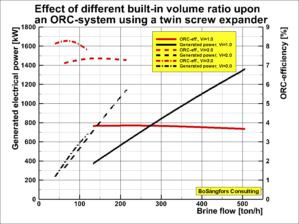
Performance as a function of brine flow
ŁŁŁŁŁŁŁŁŁŁŁŁŁŁŁŁŁŁŁŁŁŁŁŁŁŁŁŁŁŁŁŁŁŁŁŁŁŁŁŁŁŁŁŁŁŁŁŁŁŁŁŁŁŁŁŁŁŁŁŁŁŁŁŁŁŁŁŁŁŁŁŁŁŁŁŁŁŁŁŁŁŁŁŁŁŁŁŁŁŁŁŁŁŁŁŁŁŁŁŁŁŁŁŁŁŁŁŁŁŁŁŁŁŁŁŁŁŁŁŁŁŁŁŁŁŁŁŁŁŁŁŁŁŁŁŁŁŁŁ
Effect of feed pump
power consumption at different steam quality X on the generated power from a
R134a ORC-system using a Twin Screw Expander.
-----------------
Brine = Water
Coolant = Water
Working medium =R134a, 0.0 < x
<1.0 at the expander inlet
Built-in volume ratio =2.0
NOTE: This built-in volume ratio is then used in all calculations
Rotor diameter = 285 mm
Male rotor tip speed = 60 m/s
Brine temp in = 100 centigrade
Coolant temp in = 20 centigrade
Evaporation temp = (11*Brine temp + 5*Coolant temp)/16 = 95.625
centigrade
Evaporation pressure = 23.641 bar
Condensing temp = (3*Brine temp + 13*Coolant temp)/16 = 40.625 centigrade
Condensing pressure = 8.8698 bar
Pump losses in ORC system are included.
Brine pump losses are not included.
Coolant pump losses are included.
Temp. efficiency Evaporator = 90 %
Temp. efficiency Condenser = 90 %
---------------------------------------------------------------------------------------------------------------------------------
Fig 1 shows the
mass flow, feed pump consumption, shaft power and the generated electricity.
As you can see
decreasing quality X increases the mass flow, which also leads to increased feed
pump power consumption.
At steam quality
close to zero the losses caused by the feed pump are higher than the generated
shaft power.
As is obvious it is important to have a good quality x at the expander inlet.
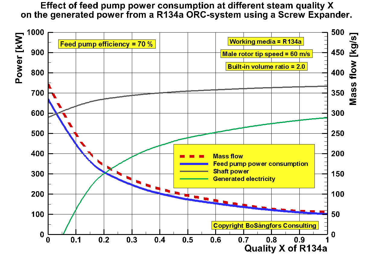
Fig.1
ŁŁŁŁŁŁŁŁŁŁŁŁŁŁŁŁŁŁŁŁŁŁŁŁŁŁŁŁŁŁŁŁŁŁŁŁŁŁŁŁŁŁŁŁŁŁŁŁŁŁŁŁŁŁŁŁŁŁŁŁŁŁŁŁŁŁŁŁŁŁŁŁŁŁŁŁŁŁŁŁŁŁŁŁŁŁŁŁŁŁŁŁŁŁŁŁŁŁŁŁŁŁŁŁŁŁŁŁŁŁŁŁ
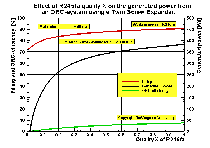
Screw
Expander Inlet Pressure Drop and itÆs Effect on
Performance as a function of R245fa inlet quality X
Input data:
Brine = Water
Coolant = Water
Built-in volume ratio =2.5, Optimized at X=1.0
NOTE: This built-in volume ratio is then used in all calculations
Rotor diameter = 285 mm
Male rotor tip speed = 60 m/s
Brine temp in = 120 centigrade
Coolant temp in = 20 centigrade
Evaporation pressure = 11.46 bar
Condensing temp = (3*Brine temp + 13*Coolant temp)/16 = 40.625 centigrade
Condensing pressure = 2.5567 bar
Pump losses in ORC system are included.
Brine pump losses are not included.
Coolant pump losses are included.
Temp. efficiency Evaporator = 90 %
Temp. efficiency Condenser = 90 %
---------------------------------------------------------------------------------------------------------------------------------
As is obvious the pressure drop is high at the opening and the closing of the inlet port due to the small areas.
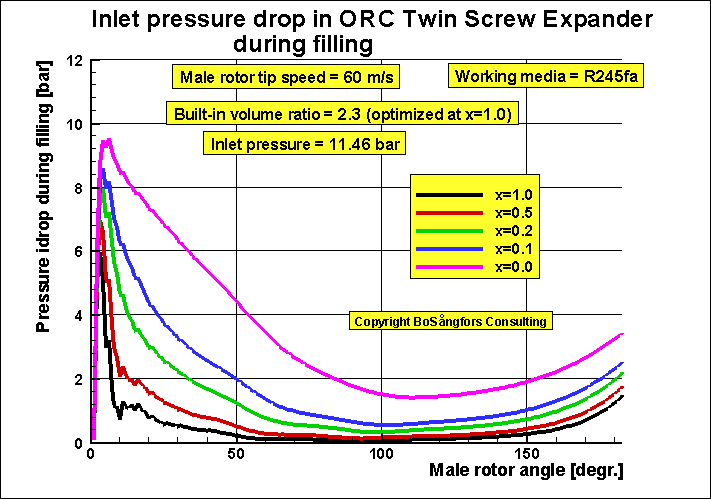
Fig 1
Fig 2 shows the shaft power as well as the filling and the adiabatic efficiency.As you can see all these parameters decrease when the quality X at the expander inlet decreases.
As is obvious it is important to have a good quality x at the expander inlet.
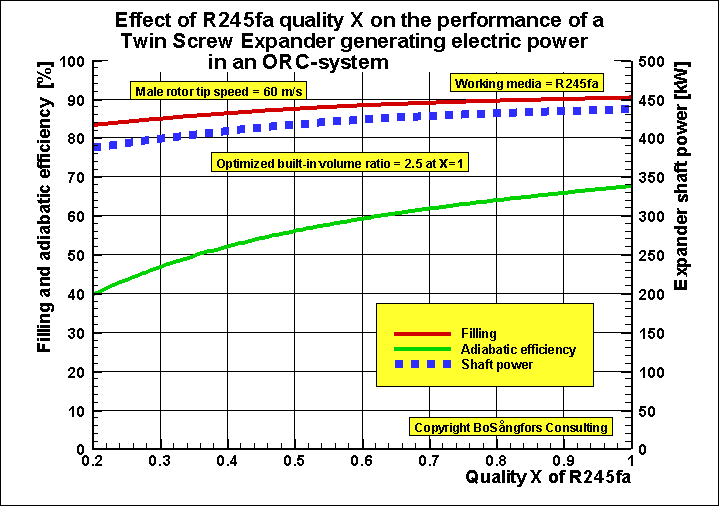
As you can see all these parameters decrease when the quality X at the expander inlet decreases.
As is obvious it is important to have a good quality x at the expander inlet.
ŁŁŁŁŁŁŁŁŁŁŁŁŁŁŁŁŁŁŁŁŁŁŁŁŁŁŁŁŁŁŁŁŁŁŁŁŁŁŁŁŁŁŁŁŁŁŁŁŁŁŁŁŁŁŁŁŁŁŁŁŁŁŁŁŁŁŁŁŁŁŁŁŁŁŁŁŁŁŁŁŁŁŁŁŁŁŁŁŁŁŁŁŁŁŁŁŁŁŁŁŁŁŁŁŁŁŁŁŁŁŁŁŁŁŁŁŁŁŁŁŁŁŁŁŁŁŁŁŁŁŁŁŁŁŁŁŁŁŁŁŁ
SOLAR COLLECTORS
ŁŁŁŁŁŁŁŁŁŁŁŁŁŁŁŁŁŁŁŁŁŁŁŁŁŁŁŁŁŁŁŁŁŁŁŁŁŁŁŁŁŁŁŁŁŁŁŁŁŁŁŁŁŁŁŁŁŁŁŁŁŁŁŁŁŁŁŁŁŁŁŁŁŁŁŁŁŁŁŁŁŁŁŁŁŁŁŁŁŁŁŁŁŁŁŁŁŁŁŁŁŁŁŁŁŁŁŁŁŁŁŁ
Influence of channel shape on Solar Collector Performance
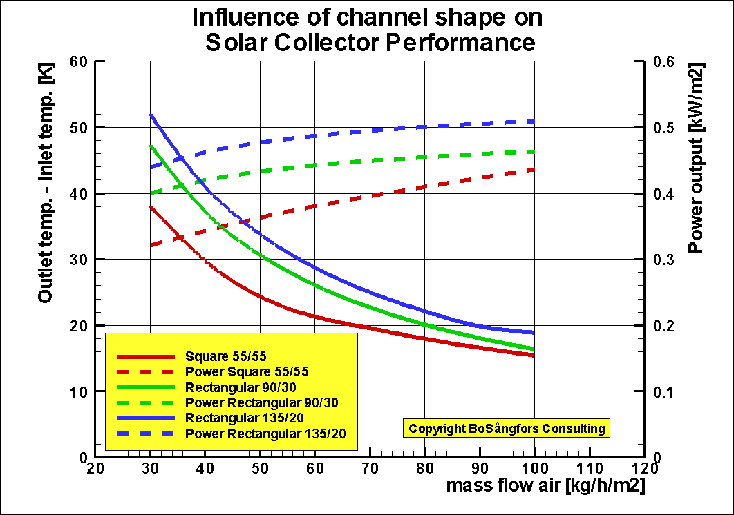
PICTURE BELOW:
-
- You increase the heat transfer surface when the ratio (length of flange/distance between flanges) increases
- T
Length of flange = 135 mm
Distance between flanges = 20 mm
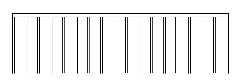
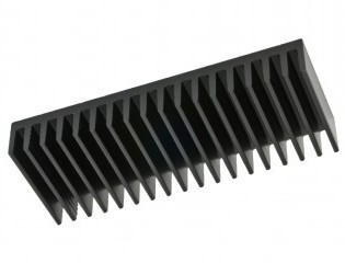
Here are examples of some standard designs that one can buy.
See also:
https://www.researchgate.net/publication/301551572_Addition_to_Influence_of_channel_shape_on_Solar_Collector_Performance
https://www.researchgate.net/publication/299599242_Influence_of_channel_shape_on_Solar_Collector_Performance
ŁŁŁŁŁŁŁŁŁŁŁŁŁŁŁŁŁŁŁŁŁŁŁŁŁŁŁŁŁŁŁŁŁŁŁŁŁŁŁŁŁŁŁŁŁŁŁŁŁŁŁŁŁŁŁŁŁŁŁŁŁŁŁŁŁŁŁŁŁŁŁŁŁŁŁŁŁŁŁŁŁŁŁŁŁŁŁŁŁŁŁŁŁŁŁŁŁŁŁŁŁŁŁŁŁŁŁŁŁŁŁŁŁŁŁŁŁŁŁŁŁŁŁŁŁŁŁŁŁŁŁŁŁŁŁŁŁŁŁŁŁŁŁŁŁŁŁŁŁŁŁŁŁŁŁŁŁŁŁŁŁŁŁŁŁŁŁŁŁŁŁŁŁ
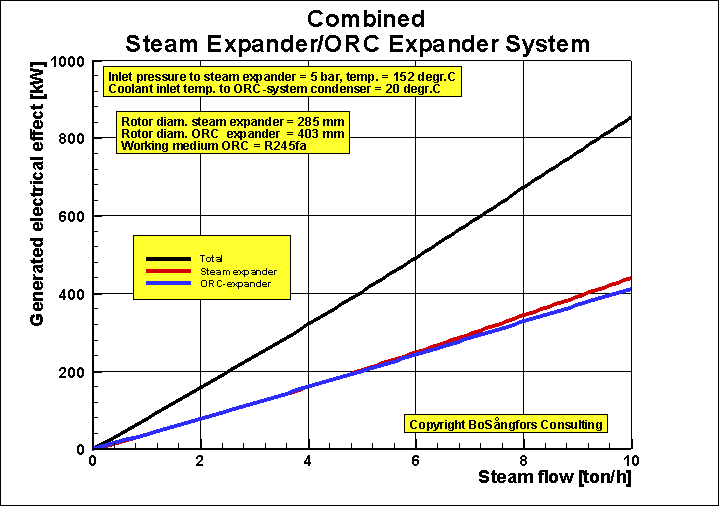
SCREW COMPRESSORS/EXPANDERS
Estimated Performance of a Waste Heat Recovery System
Stage 1: Steam Screw Expander
Stage 2: ORC using Screw Expander
Stage 1: Steam Screw Expander in above Combined System
Stage 2: ORC using Screw Expander in above Combined System
Change the working medium in stage 2 from R134a to R245fa.
Then it is necessary to change the rotor diam. from 285 mm to 403 mm
to get the same performance.
Why not use a turbine instead, since the expansion takes place in the superheated region?
Any objections?
ŁŁŁŁŁŁŁŁŁŁŁŁŁŁŁŁŁŁŁŁŁŁŁŁŁŁŁŁŁŁŁŁŁŁŁŁŁŁŁŁŁŁŁŁŁŁŁŁŁŁŁŁŁŁŁŁŁŁŁŁŁŁŁŁŁŁŁŁŁŁŁŁŁŁŁŁŁŁŁŁŁŁŁŁŁŁŁŁŁŁŁŁŁŁŁŁŁŁŁŁŁŁŁŁŁŁŁŁŁŁŁŁ
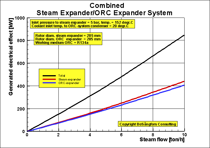
Using two Helical Screw Expanders of same size for generation of
Power from a 2 stage Heat Recovery System
Stage 1: Steam Screw Expander, Diam. = 285 mm
Stage 2: ORC using
R245fa Screw Expander, Diam. = 285 mm
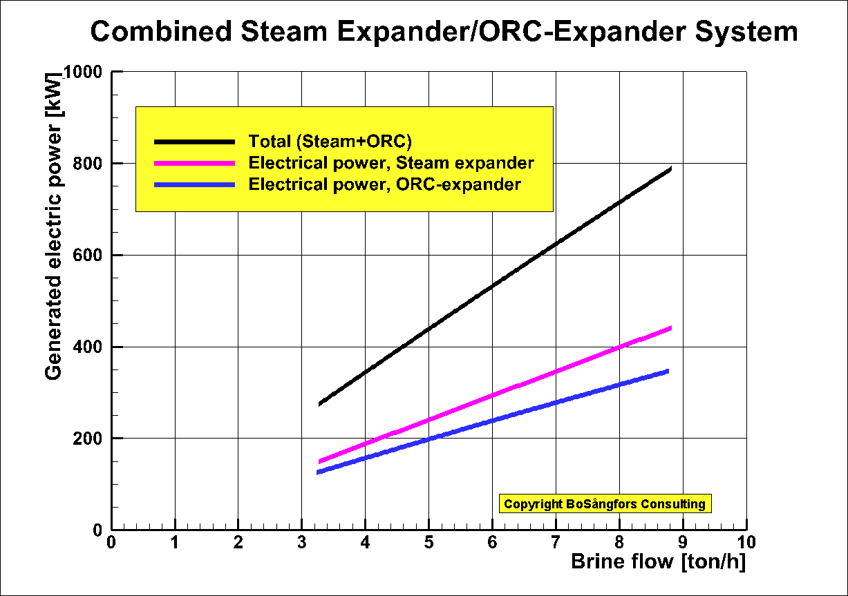
Fig.1
Stage 1: Steam Screw Expander in above Combined System
Rotor diameter = 285 mmBuilt-in volume ratio = 2.0
Inlet/Outlet pressure = 5/1 bar
Inlet/Outlet temperature 151.8/99.6 centigrade
Male rotor tip speed = 41.5 < Vtip < 124.5 m/s
Generator efficiency = 0.95
Fig.2 shows that the generated effect and the adiabatic efficiency as a function of the steam flow leaving the steam expander.
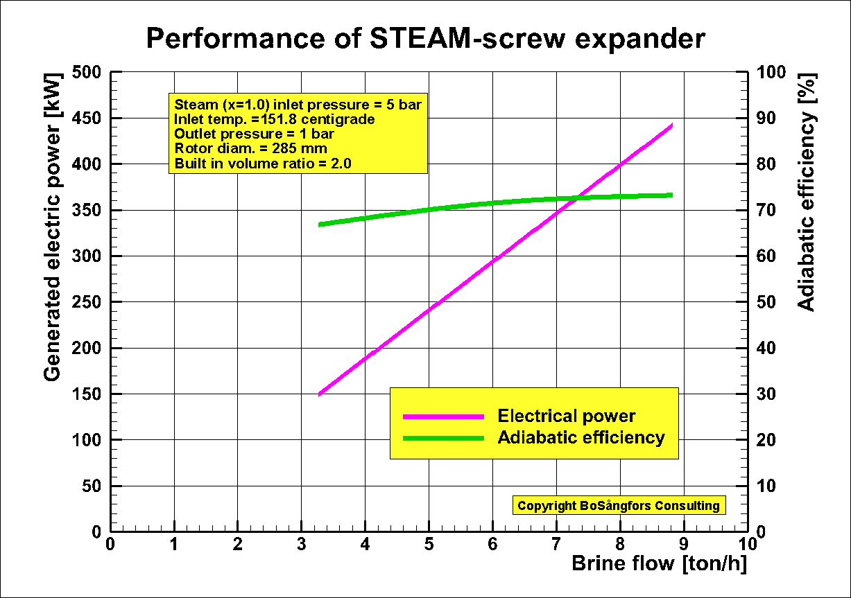
Fig.2
Stage 2: ORC using Screw Expander in above Combined System
Rotor diameter = 285 mmBuilt-in volume ratio = 1.9
Male rotor tip speed = 41.5 < Vtip < 124.5 m/s
Brine = Water of steam quality x=0.92 leaving the steam expander stage 1
Coolant = Water
Brine temp in = 100 centigrade
Coolant temp in = 20 centigrade
Working medium =R245fa
R245fa quality x at expander inlet = 1.0
Evaporation temp = (11*Brine temp + 5*Coolant temp)/16 = 75 centigrade
Evaporation pressure = 6.9510 bar
Condensing temp = (3*Brine temp + 13*Coolant temp)/16 = 35 centigrade
Condensing pressure = 2.1172 bar
Temp. efficiency Evaporator = 90 %
Temp. efficiency Condenser = 90 %
Generator efficiency = 0.95
Pump losses in ORC system are included.
Brine pump losses are not included.
Coolant pump losses are included.
Fig 3 shows generated power and ORC-efficiency.
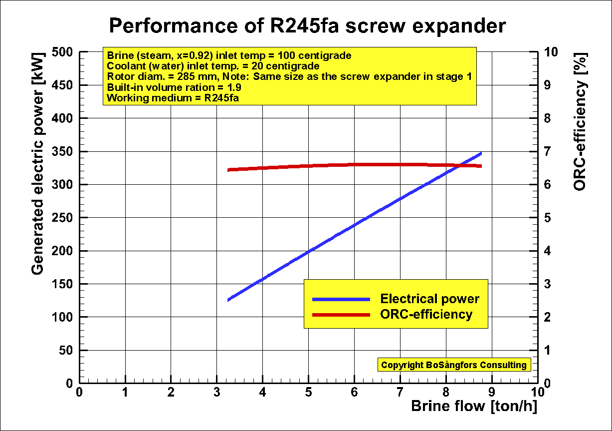
Fig.3
ŁŁŁŁŁŁŁŁŁŁŁŁŁŁŁŁŁŁŁŁŁŁŁŁŁŁŁŁŁŁŁŁŁŁŁŁŁŁŁŁŁŁŁŁŁŁŁŁŁŁŁŁŁŁŁŁŁŁŁŁŁŁŁŁŁŁŁŁŁŁŁŁŁŁŁŁŁŁŁŁŁŁŁŁŁŁŁŁŁŁŁŁŁŁŁŁŁŁŁŁŁŁŁŁŁŁŁŁŁŁŁŁŁŁŁŁŁŁŁŁŁŁŁŁŁŁŁŁŁŁŁŁŁŁŁŁŁŁŁŁŁŁŁŁŁŁŁŁŁŁŁŁŁŁŁŁŁŁŁŁŁŁŁŁŁŁŁŁŁŁŁŁŁ
Improvement of
ōUsing two
Helical Screw Expanders of same size for generation of Power from a
2 stage
Heat Recovery Systemö
Stage 2: ORC using R245fa Screw
Expander, Diam. = 285 mm
The two screw expanders
in this system are dry expanders of the same size, namely diam. = 285mm.
Tip speeds: Steam
expander 41.5 to 124.5 m/s, R245fa ORC-expander 30 to 90 m/s
Fig.1 shows the generated effect as a function of the brine flow in the system.
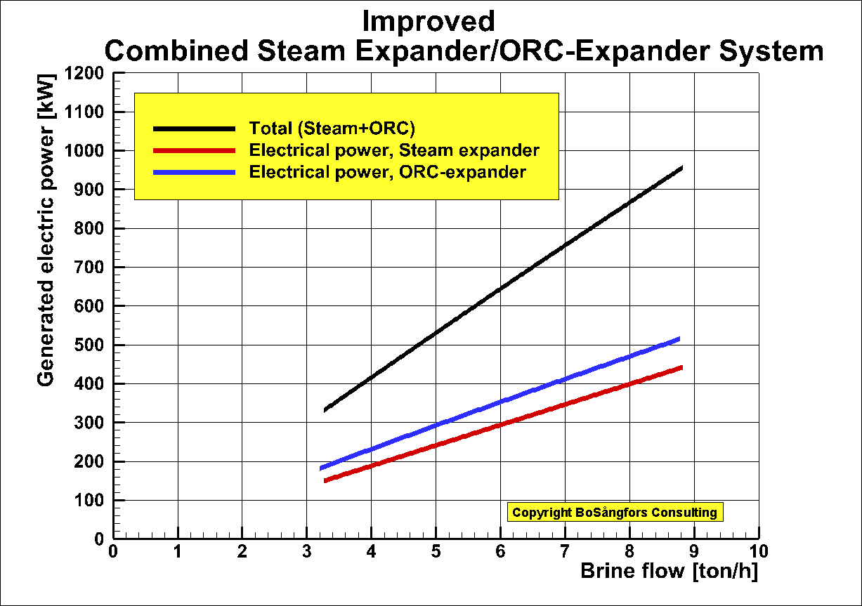
Fig.1.
Stage 1: Steam Screw Expander in
above Combined System
Rotor diameter = 285 mm
Built-in volume ratio = 2.0
Inlet/Outlet pressure = 5/1 bar,
Inlet/Outlet temperature 151.8/102.9 centigrade
Male rotor tip speed = 41.5 < Vtip < 124.5 m/s
Generator efficiency = 0.95
Fig.2 shows that the generated effect and the adiabatic efficiency as a function of the brine (steam) flow leaving the steam expander.
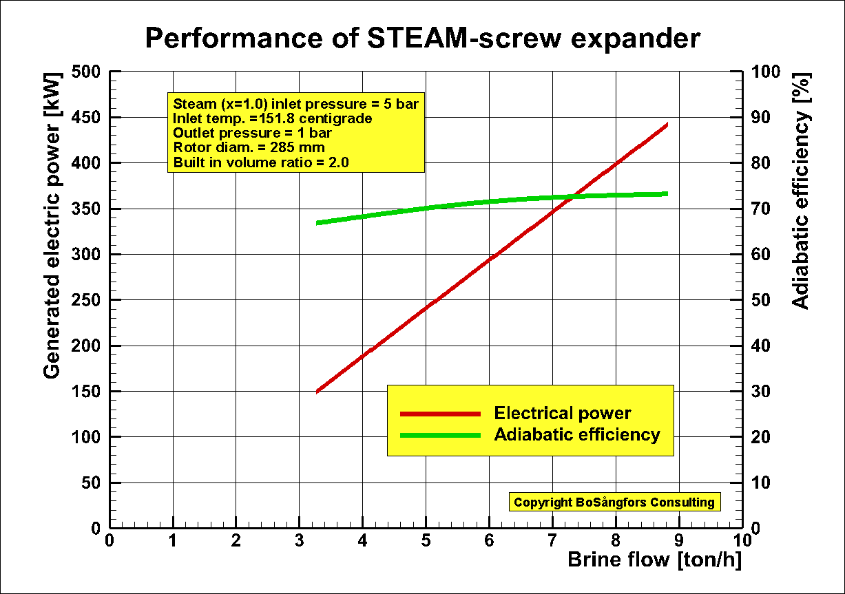
Fig.2
Stage 2: ORC using Screw Expander in
above Combined System
Rotor diameter = 285 mm
Built-in volume ratio = 1.9
Male rotor tip speed = 30 < Vtip < 90 m/s
Brine = Steam of temperature 102.9 centigrade leaving the
steam expander stage 1
Coolant = Water
Brine temp in = 102.9 centigrade
Coolant temp in = 20 centigrade
Working medium =R245fa
R245fa quality x at expander inlet = 1.0
Evaporation temp = 85 centigrade
Evaporation pressure = 8.9278 bar
Condensing temp = 35 centigrade
Condensing pressure = 2.1172 bar
Temp. efficiency (Evaporator +Preheater) = 90 %
Temp. efficiency Condenser = 90 %
Generator efficiency = 0.95
Pump losses in ORC system are included.
Brine pump losses are not included.
Coolant pump losses are included.
Fig 3 shows generated power and ORC-efficiency.
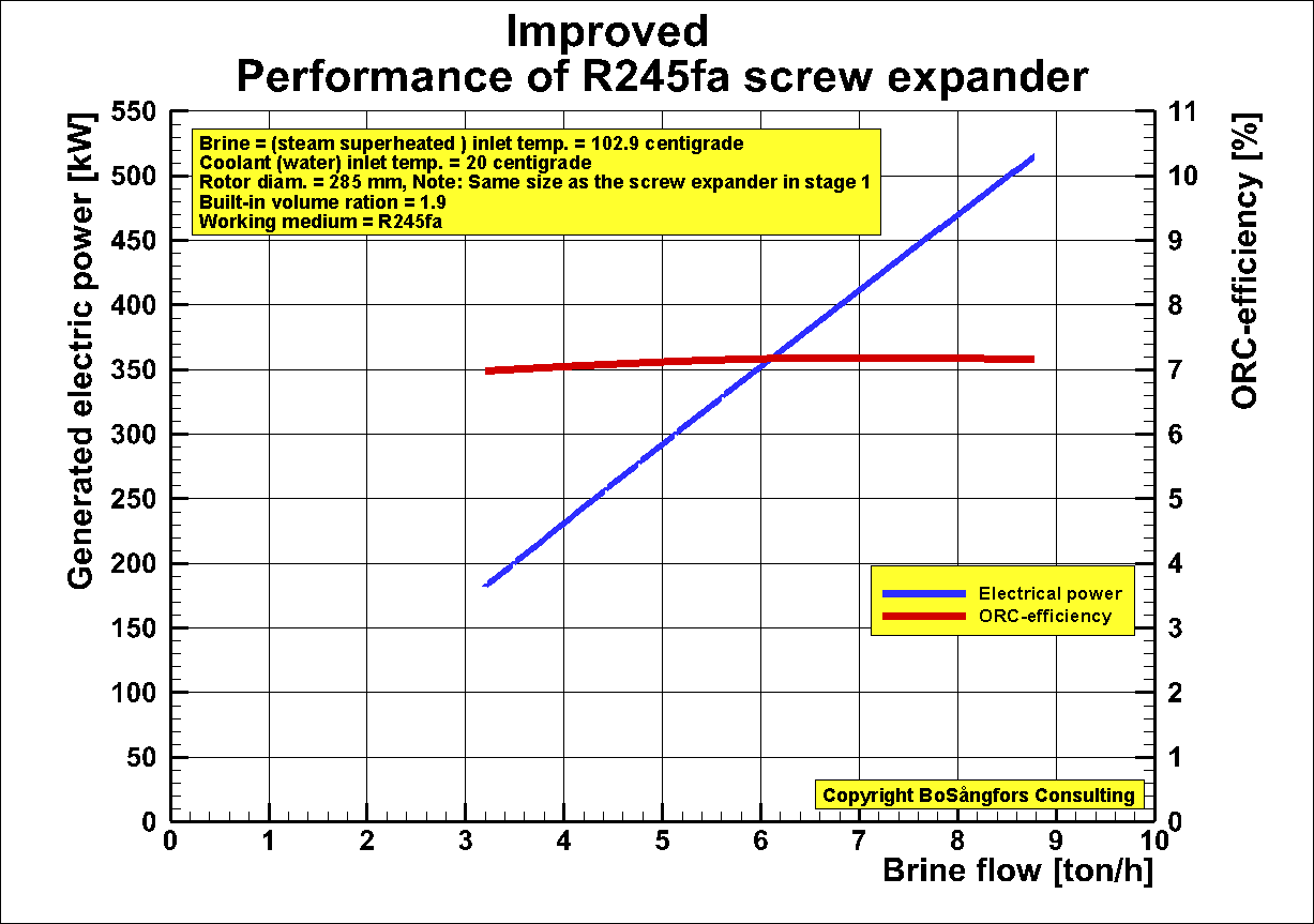
Fig.3
ŁŁŁŁŁŁŁŁŁŁŁŁŁŁŁŁŁŁŁŁŁŁŁŁŁŁŁŁŁŁŁŁŁŁŁŁŁŁŁŁŁŁŁŁŁŁŁŁŁŁŁŁŁŁŁŁŁŁŁŁŁŁŁŁŁŁŁŁŁŁŁŁŁŁŁŁŁŁŁŁŁŁŁŁŁŁŁŁŁŁŁŁŁŁŁŁŁŁŁŁŁŁŁŁŁŁŁŁŁŁŁŁ
Increased brine flow
and decreased output of electrical power due to decreased R245fa steam quality x
from an ORC-system using a Twin Screw Expander.
This graph is just to show the importance of having a good steam quality
at the screw expander inlet.
One can say that this is typical for all displacement machines - not
only screw expanders.
-----------------
Brine = Water
Coolant = Water
Working medium =R245fa
R245fa quality x at expander inlet = 1.0, 0.5 and 0.25
Built-in volume ratio = 1.9, Optimized at x=1.0
Rotor diameter = 285 mm
Brine temp in = 100 centigrade
Coolant temp in = 20 centigrade
Evaporation temp = (11*Brine temp + 5*Coolant temp)/16 = 75 centigrade
Evaporation pressure = 6.9510 bar
Condensing temp = (3*Brine temp + 13*Coolant temp)/16 = 35 centigrade
Condensing pressure = 2.1172 bar
Pump losses in ORC system are included.
Brine pump losses are not included.
Coolant pump losses are included.
Temp. efficiency Evaporator = 90 %
Temp. efficiency Condenser = 90 %
---------------------------------------------------------------------------------------------------------------------------------
Fig 1 shows the
generated power and ORC-efficiency. As you can see all these parameters decrease
when the quality X at the expander inlet decreases.
As is obvious it is important to have a good quality x at the expander inlet.
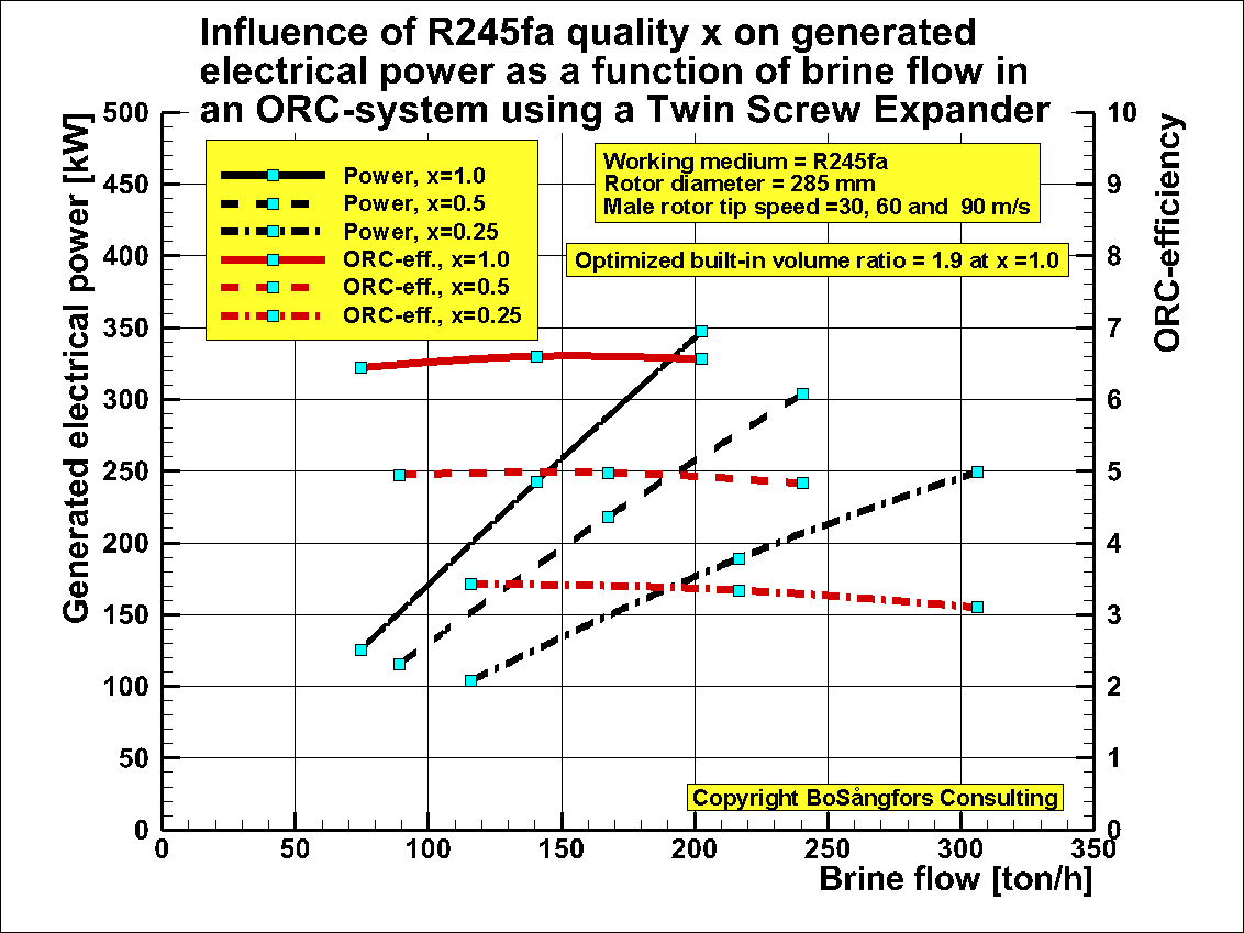
Fig. 1
ŁŁŁŁŁŁŁŁŁŁŁŁŁŁŁŁŁŁŁ-------------------------------------------------------------------ŁŁŁŁŁŁŁŁŁŁŁŁŁŁŁŁŁŁŁŁŁŁŁŁŁŁŁŁŁŁŁŁŁŁŁŁŁŁŁŁŁŁŁŁŁŁŁŁŁŁŁŁŁŁŁŁŁŁŁŁŁŁŁŁŁŁŁŁŁŁŁŁŁŁŁŁŁŁŁŁŁŁŁŁŁŁŁŁŁŁŁŁŁŁŁŁŁŁŁŁŁŁŁŁŁŁŁŁŁŁŁŁŁŁŁŁŁŁŁŁ
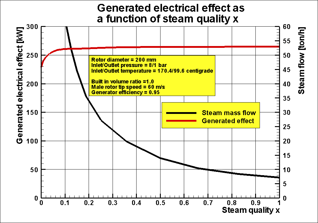
Adjusting of Steam
Screw Expander rotor tip speed in order to keep the inlet mass flow constant at
different inlet steam quality X.
This is an addition to the data file ōImportance of having good steam quality x at the inlet of a Steam Screw Expander generating electric powerö and ōEffect of inlet steam quality X if the inlet steam mass flow is constantö.
In these calculations
the steam mass flow is kept constant by changing the male rotor tip speed at
different steam quality x.
As can be seen the
generated power decreases with decreasing inlet steam quality x.
Other
data are:
Rotor
diameter = 200 mm
Inlet/Outlet pressure = 8/1 bar at all calculated steam quality points
Inlet/Outlet temperature 170.4/99.6 centigrade at all calculated steam quality
points
Inlet steam mass flow = 2.05 ton/h in all
calculations.
Built-in volume ratio = 3.2, optimized at steam quality x =1.0
Generator efficiency = 0.95
Fig.1 shows that the generated effect decreases with decreasing steam quality.
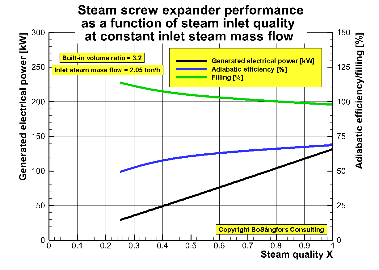
Fig. 1
Fig. 2
shows the variation of the male rotor tip speed to get the inlet steam mass flow
to be constant,
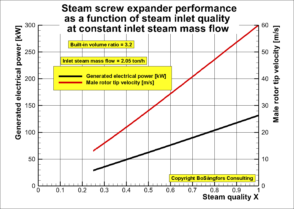
Fig. 2
ŁŁŁŁŁŁŁŁŁŁŁŁŁŁŁŁŁŁŁ-------------------------------------------------------------------ŁŁŁŁŁŁŁŁŁŁŁŁŁŁŁŁŁŁŁŁŁŁŁŁŁŁŁŁŁŁŁŁŁŁŁŁŁŁŁŁŁŁŁŁŁŁŁŁŁŁŁŁŁŁŁŁŁŁŁŁŁŁŁŁŁŁŁŁŁŁŁŁŁŁŁŁŁŁŁŁŁŁŁŁŁŁŁŁŁŁŁŁŁŁŁŁŁŁŁŁŁŁŁŁŁŁŁŁŁŁŁŁŁŁŁŁŁŁŁŁ
New version of Effect
of inlet steam quality X if the inlet steam mass flow is constant.
This is an
addition to the data file ōImportance of having good steam quality x at the
inlet of a Steam Screw Expander generating electric powerö and ōEffect of inlet
steam quality X if the inlet steam mass flow is constantö earlier uploaded on
Research Gate
In these calculations the steam mass flow is kept constant by changing the built-in volume ratio.
As can be seen the
generated power and the filling decreases with decreasing inlet steam quality.
The adiabatic efficiency is maximum at x=3.0
Other
data are:
Rotor
diameter = 200 mm
Inlet/Outlet pressure = 8/1 bar at all calculated steam quality points
Inlet/Outlet temperature 170.4/99.6 centigrade at all calculated steam quality
points
Inlet steam mass flow = 7.2 ton/h in all
calculations.
Male rotor tip speed = 60 m/s
Generator efficiency = 0.95
Fig.1 shows that the generated effect and the filling decreases with decreasing
steam quality.
The adiabatic efficiency is maximum at x=0.3.
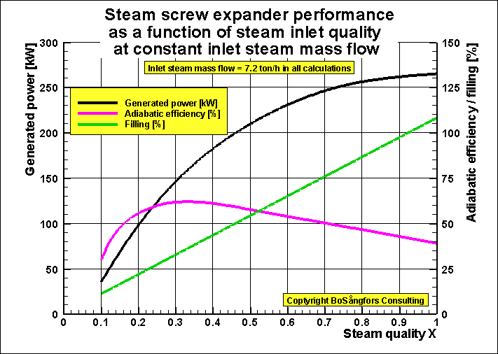
Fig. 1
Fig. 2 shows the variation of the built-in volume ratio to get the inlet steam mass flow to be constant
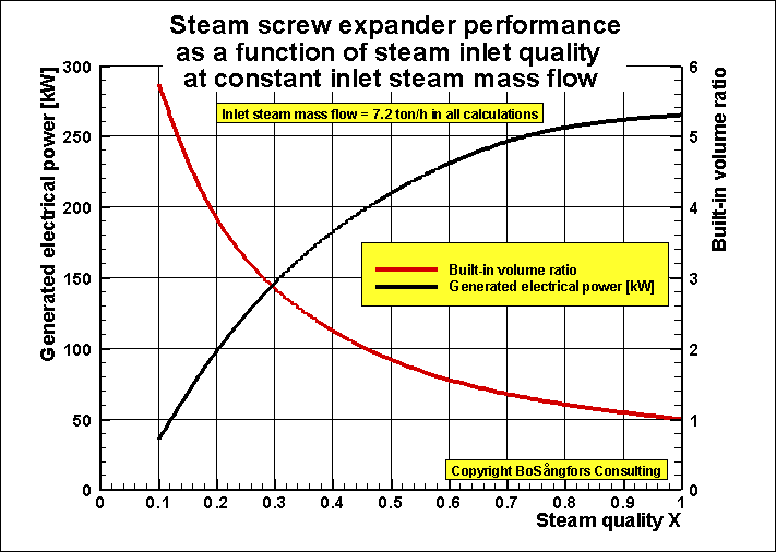
Fig. 2
ŁŁŁŁŁŁŁŁŁŁŁŁŁŁŁŁŁŁŁ-------------------------------------------------------------------ŁŁŁŁŁŁŁŁŁŁŁŁŁŁŁŁŁŁŁŁŁŁŁŁŁŁŁŁŁŁŁŁŁŁŁŁŁŁŁŁŁŁŁŁŁŁŁŁŁŁŁŁŁŁŁŁŁŁŁŁŁŁŁŁŁŁŁŁŁŁŁŁŁŁŁŁŁŁŁŁŁŁŁŁŁŁŁŁŁŁŁŁŁŁŁŁŁŁŁŁŁŁŁŁŁŁŁŁŁŁŁŁŁŁŁŁŁŁŁŁ
Effect of steam quality X
upon the performance of an ORC-system,
which uses a screw expander for driving a generator producing electrical power
In order to give more information about the effects of
various steam quality X,
when using a screw expander in an ORC-system these
calculations are presented.
This data set presents 2 graphs, where fig.1 shows the
performance as a function of the male rotor tip speed and fig.2
the performance as a function of the brine flow.
The expander is a dry screw expander with synchronizing
bearings
Rotor diameter = 285 mm
Built in volume ratio = 1.8, which is optimized at male
rotor tip speed = 60 m/s
Brine = Water
Coolant = Water
Brine temp = 90 centigrade
Coolant temp = 20 centigrade
Evaporation temp. = (11*Brine temp + 5*Coolant temp)/16
= 68.125 centigrade
Condensing temp = (3*Brine temp + 13*Coolant temp)/16 =
33.125 centigrade
These temperatures are valid for all presented
calculations.
Pump losses in ORC system are included.
Brine pump losses are not included.
Coolant pump losses are included.
Temperature efficiency Evaporator = 90 %
Temperature efficiency Condenser = 90 %
Working media = R134a
Generator efficiency = 95 %
Calculation results:
As can be seen from fig. 1 and 2 the generated power
decreases with decreasing quality X.
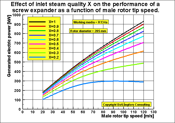
Fig. 1. Performance as a function of male rotor tip speed
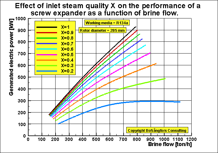
Fig. 2. Performance as a function of brine flow
ŁŁŁŁŁŁŁŁŁŁŁŁŁŁŁŁŁŁŁŁŁŁŁŁŁŁŁŁŁŁŁŁŁŁŁŁŁŁŁŁŁŁŁŁŁŁŁŁŁŁŁŁŁŁŁŁŁŁŁŁŁŁŁŁŁŁŁŁŁŁŁŁŁŁŁŁŁŁŁŁŁŁŁŁŁŁŁŁŁŁŁŁŁŁŁŁŁŁŁŁŁŁŁŁŁŁŁŁŁŁŁŁŁŁŁŁŁŁŁŁŁŁŁŁŁŁŁŁŁŁŁŁŁŁŁŁŁŁŁ
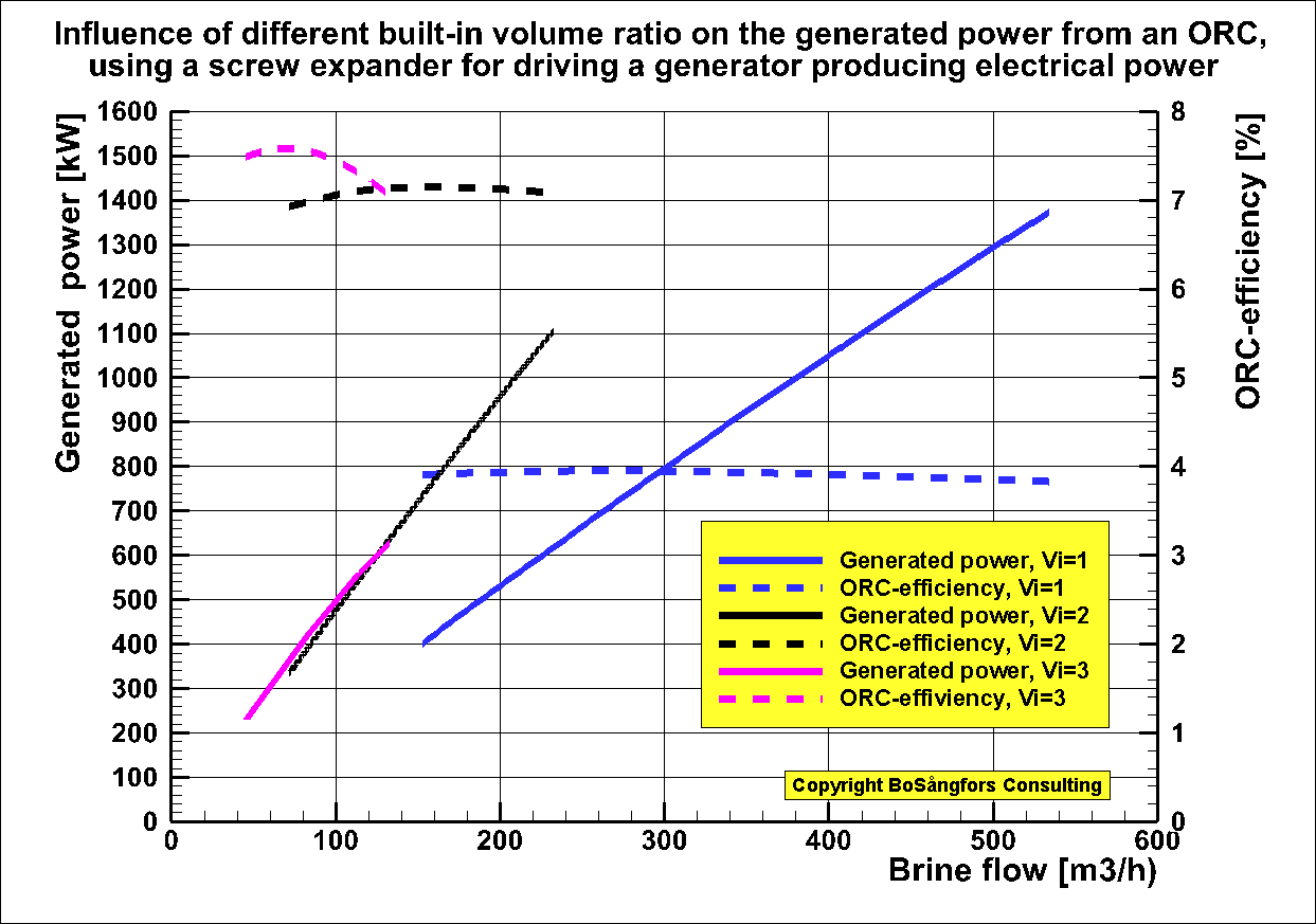
Effect of different built-in volume ratio
upon the performance of an ORC-system,
which uses a helical screw expander for
driving a generator producing electrical power.
In order to give more information about the effects of
various built-in volume ratio Vi, when using a screw expander in an
ORC-system these calculations are presented.
This data
set presents 2 graphs, where fig.1 shows the performance as a function of the
male rotor tip speed and fig.2 the performance as a function of the brine flow.
The
expander is a dry screw expander with synchronizing bearings
Rotor
diameter = 285 mm
Built in
volume ratio = 3 cases, namely 1, 2, 3
Brine =
Water
Coolant =
Water
Brine
temp = 90 centigrade
Coolant
temp = 20 centigrade
Evaporation temp. = (11*Brine temp + 5*Coolant temp)/16
Condensing temp = (3*Brine temp + 13*Coolant temp)/16
These
temperatures are valid for all presented calculations.
Pump
losses in ORC system are included.
Brine
pump losses are not included.
Coolant
pump losses are included.
Working media = R134a
Quality x = 1.0 at the screw expander inlet
Calculation results:
As can be
seen from fig. 1 the built-in volume ratio = 1 gives the highest production of
power, but the ORC-efficiency is not so high.
At Vi=2 the produced power is lower, but now the efficiency has increased and is very close to the optimized Vi=1.8.
At Vi=3 the produced power begins to decrease after male rotor tip speed = 80 m/s.
Please note that the ORC-efficiency decreases when the tip speed increases.
This is due to the increased pressure drop at the expander inlet.
Fig. 1. Performance as a function of male rotor tip speed
As can be seen from fig.2 the operational range is
strongly reduced when Vi
is increased.
For Vi = 3 the
pressure drop loss at the inlet is so high that the operational range is
extremely reduced.
At brine flow above 130 m3/h
the generated effect starts to decrease.
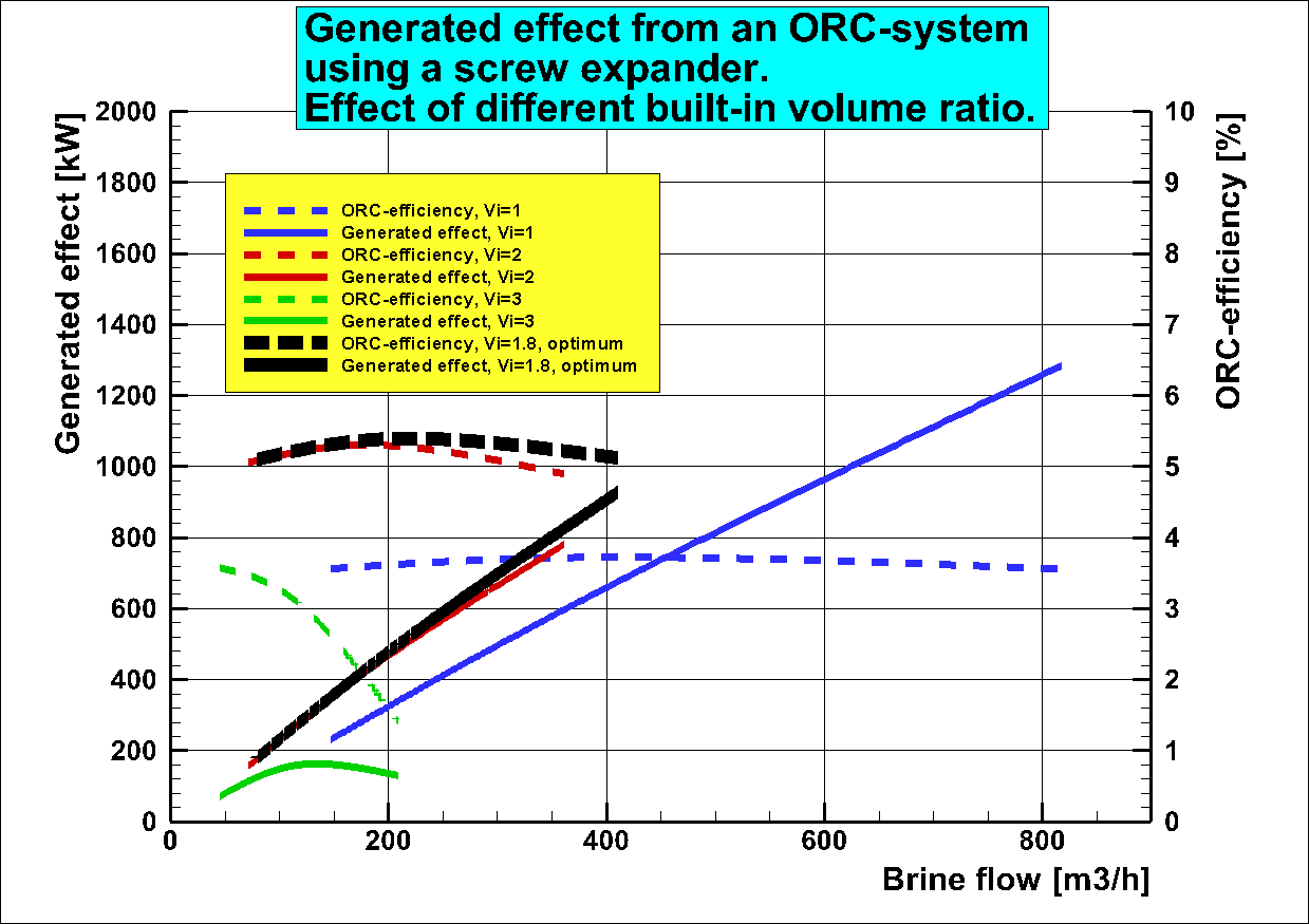
Fig. 2. Performance as a function of brine flow
ŁŁŁŁŁŁŁŁŁŁŁŁŁŁŁŁŁŁŁŁŁŁŁŁŁŁŁŁŁŁŁŁŁŁŁŁŁŁŁŁŁŁŁŁŁŁŁŁŁŁŁŁŁŁŁŁŁŁŁŁŁŁŁŁŁŁŁŁŁŁŁŁŁŁŁŁŁŁŁŁŁŁŁŁŁŁŁŁŁŁŁŁŁŁŁŁŁŁŁŁŁŁŁŁŁŁŁŁŁŁŁŁŁŁŁŁŁŁŁŁŁŁŁŁŁŁŁŁŁŁŁŁŁŁŁŁŁŁŁ
Influence of different built-in volume ratio
on the generated power from of an ORC, using
a screw expander for
driving a generator producing electrical power.
In order to give more information about
the effects of various built-in volume ratio Vi, when
using a screw expander in an ORC-system these calculations are
also presented.
The presented graph shows the generated power and the
ORC-efficiency a function of the brine flow.
The
expander is a dry screw expander with synchronizing bearings
Rotor diameter = 285 mm
Male rotor tip speed is from 30 m/s
up to 110 m/s.
The present results are for built-in volume ratio 1, 2 and 3
Brine =
Water
Coolant =
Water
Brine
temp = 130 centigrade
Coolant
temp = 20 centigrade
Evaporation temp. = (11*Brine temp + 5*Coolant temp)/16
Condensing temp = (3*Brine temp + 13*Coolant temp)/16
These
temperatures are valid for all presented calculations.
Pump
losses in ORC system are included.
Brine
pump losses are not included.
Coolant
pump losses are included.
Working media = R236fa
Quality x = 1.0 at the screw expander inlet
Calculation results:
As can be seen from the graph the built-in volume ration Vi = 1
gives the highest production of power but the ORC-efficiency is
not so high.
At Vi =2 the produced power is lower, but now the ORC-efficiency
has increased.
At Vi =3 the
produced power is even more low and the ORC-efficiency as high as 7.6 % at 60 m3/h brine flow.
The operational range is strongly reduced when Vi is reduced.
Performance as a function of brine flow
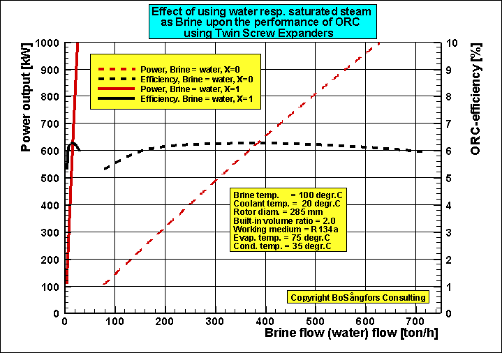
BoSÕngfors Consulting, Sweden
This picture shows the effect of using saturated steam instead of water.
As can be seen the use of saturated steam is much more efficient than the use of water.
ŁŁŁŁŁŁŁŁŁŁŁŁŁŁŁŁŁŁŁŁŁŁŁŁŁŁŁŁŁŁŁŁŁŁŁŁŁŁŁŁŁŁŁŁŁŁŁŁŁŁŁŁŁŁŁŁŁŁŁŁŁŁŁŁŁŁŁŁŁŁŁŁŁŁŁŁŁŁŁŁŁŁŁŁŁŁŁŁŁŁŁŁŁŁŁŁŁŁŁŁŁŁŁŁŁŁŁŁŁŁŁŁŁŁŁŁŁŁŁŁŁŁŁŁŁŁŁŁŁŁŁŁŁŁŁŁŁŁŁŁŁŁ
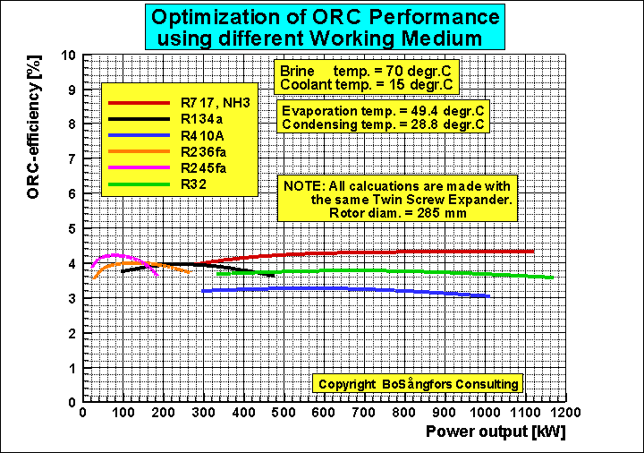
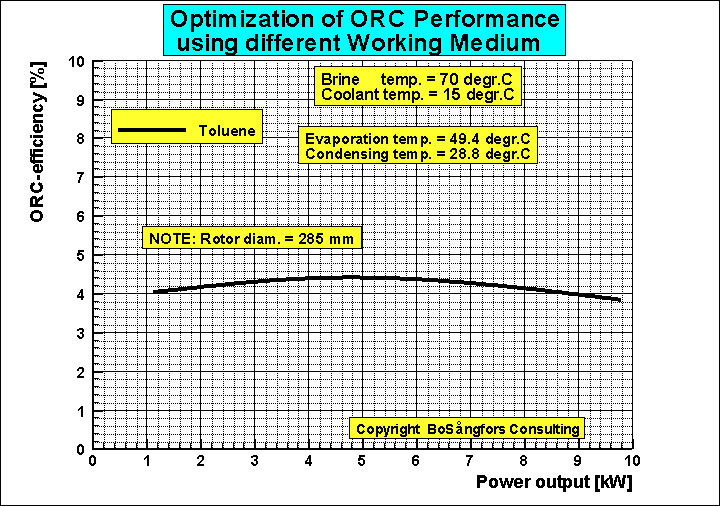
Influence of different working medium on ORC Performance
Brine = water
Coolant = water
ŁŁŁŁŁŁŁŁŁŁŁŁŁŁŁŁŁŁŁŁŁŁŁŁŁŁŁŁŁŁŁŁŁŁŁŁŁŁŁŁŁŁŁŁŁŁŁŁŁŁŁŁŁŁŁŁŁŁŁŁŁŁŁŁŁŁŁŁŁŁŁŁŁŁŁŁŁŁŁŁŁŁŁŁŁŁŁŁŁŁŁŁŁŁŁŁŁŁŁŁŁŁŁŁŁŁŁŁŁŁŁŁŁŁŁŁŁŁŁŁŁŁŁŁŁŁŁŁŁŁŁŁŁŁŁŁ
Effect of Brine outlet temperature on the needed Brineflowin an ORC-systeem using a Twin Screw Expander
As
is well known it is important to have a good heat transfer from the brine to the
working media.
The intention of this short data set is to show how the brine outlet temperature
effects the needed brine flow.
-----------------
Brine = Water
Coolant = Water
Working medium =Ammonia, x=1.0 at the expander inlet
Built-in volume ratio =2.0
Rotor diameter = 285 mm
Male rotor tip speed = 60 m/s
Brine temp in = 100 centigrade
Coolant temp in = 20 centigrade
Evaporation temp = 80 centigrade
Evaporation pressure = 41.42 bar
Condensing temp = 30 centigrade
Condensing pressure = 11.67 bar
Pump losses in ORC system are included.
Brine pump losses are not included.
Coolant pump losses are included.
Temp. efficiency Evaporator = 25-100 %
Temp. efficiency Condenser = 90 %
Generated power = 1397.7 kW
ORC-efficiency = 8.00 %
---------------------------------------------------------------------------------------------------------------------------------
Fig 1 shows the
needed brine flow as a function of the brine outlet temperature.
As is obvious it is important to have preheater and evaporator with good heat transfer.
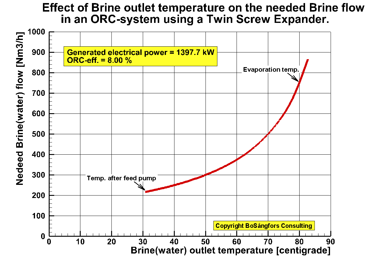
Fig.1
ŁŁŁŁŁŁŁŁŁŁŁŁŁŁŁŁŁŁŁŁŁŁŁŁŁŁŁŁŁŁŁŁŁŁŁŁŁŁŁŁŁŁŁŁŁŁŁŁŁŁŁŁŁŁŁŁŁŁŁŁŁŁŁŁŁŁŁŁŁŁŁŁŁŁŁŁŁŁŁŁŁŁŁŁŁŁŁŁŁŁŁŁŁŁŁŁŁŁŁŁŁŁŁŁŁŁŁŁŁŁŁŁŁŁŁŁŁŁŁŁŁŁŁŁŁŁŁŁŁŁŁŁŁŁŁŁŁŁŁŁŁ
Effect of not having the right coolant flow upon the performance of an ORC-system when using a screw expander.
Fig 1 and 2 show what happens if
you change the brine flow but have the coolant flow constant. As is obvious it
is important to have enough coolant flow if you want an efficient ORC
performance.
Brine =
Water
Coolant = Water
Working medium =R134a, x=1.0 at
expander inlet
Built in volume ratio =1.8
Brine temp in = 90 degr.C
Brine flow : See fig 1 and fig 2.
Coolant temp in = 20 degr.C
Coolant flow =
See fig 2. Showing the perfect and the unchanged condition
R134a, x=1.0
Built in volume ratio =1.8
Brine temp in = 90 degr.C
Brine flow : See graph
Evaporationtemp = (11*Brinetemp + 5*Coolanttemp)/16
Condensingtemp = (3*Brinetemp + 13*Coolanttemp)/16
This
value of the condensing temp. is valid for the perfect condition.
At
constant cooling flow see fig 2.
Pump losses in ORC system are included.
Brine pump losses are not included.
Coolant pump losses are included.
Temp. efficiency Evaporator = 90 %
Temp. efficiency Condenser = 90 %
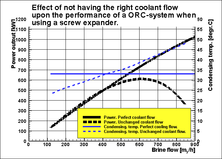
Fig.1
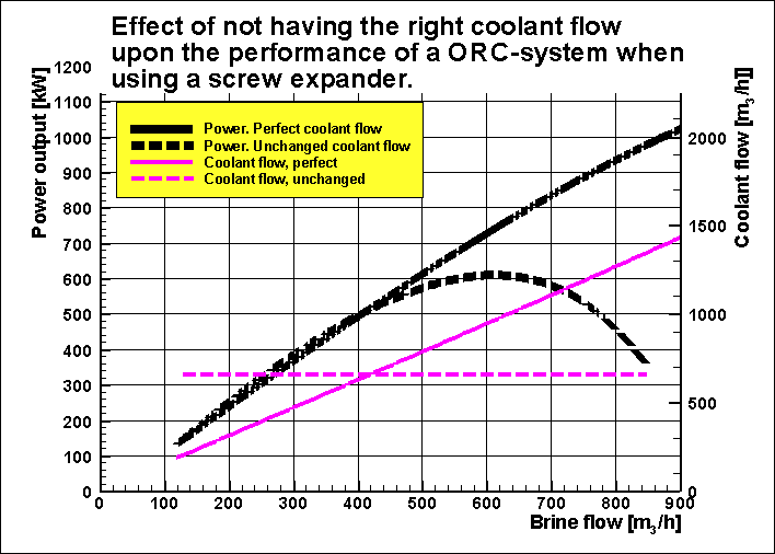
Fig.2
ŁŁŁŁŁŁŁŁŁŁŁŁŁŁŁŁŁŁŁŁŁŁŁŁŁŁŁŁŁŁŁŁŁŁŁŁŁŁŁŁŁŁŁŁŁŁŁŁŁŁŁŁŁŁŁŁŁŁŁŁŁŁŁŁŁŁŁŁŁŁŁŁŁŁŁŁŁŁŁŁŁŁŁŁŁŁŁŁŁŁŁŁŁŁŁŁŁŁŁŁŁŁŁŁŁŁŁŁŁŁŁŁŁŁŁŁŁŁŁŁŁŁŁŁŁŁŁŁŁŁŁŁŁŁŁŁŁŁŁŁŁ
Fig 1 shows what happens if you change the steam quality x at the inlet of the
screw expander. As you can see the generated power as well as the ORC-efficiency
decreases as x decreases, but the brine flow increases.
As is obvious it is important to have a good quality x at the expander inlet.
Brine = Water
Coolant = Water
Working medium =R245a, 0.2 < x <1.0 at the expander inlet
Built-in volume ratio =2.0, NOTE: This is the optimized built-in volume ratio in
all calculations
Rotor diameter = 403 mm
Male rotor tip speed = 54 m/s
Brine temp in = 100 centigrade
Coolant temp in = 20 centigrade
Evaporation temp = (11*Brine temp + 5*Coolant temp)/16 = 75 centigrade
Evaporation pressure = 6.95 bar
Condensing temp = (3*Brine temp + 13*Coolant temp)/16 = 35 centigrade
Condensing pressure = 2.12 bar
Pump losses in ORC system are included.
Brine pump losses are not included.
Coolant pump losses are included.
Temp. efficiency Evaporator = 90 %
Temp. efficiency Condenser = 90 %
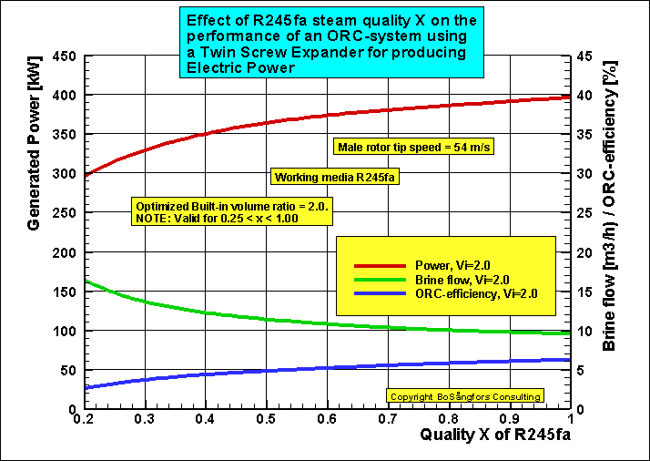
Fig
1
ŁŁŁŁŁŁŁŁŁŁŁŁŁŁŁŁŁŁŁŁŁŁŁŁŁŁŁŁŁŁŁŁŁŁŁŁŁŁŁŁŁŁŁŁŁŁŁŁŁŁŁŁŁŁŁŁŁŁŁŁŁŁŁŁŁŁŁŁŁŁŁŁŁŁŁŁŁŁŁŁŁŁŁŁŁŁŁŁŁŁŁŁŁŁŁŁŁŁŁŁŁŁŁŁŁŁŁŁŁŁŁŁŁŁŁŁŁŁŁŁŁŁŁŁŁŁŁŁŁŁŁŁŁŁŁŁŁŁŁŁŁ
Effect of change of Steam Quality X in a Steam Screw
Expander
In order to find
out the effect of the variation of Steam Quality in a screw expander this
investigation was made.It is assumed that the change is immediate. I.e. no time
factor is taken into consideration, which means that the presented effect is
maximum.
The values for the steam quality are taken from
the program Refprop.
Example:
Steam flow = 8 ton/h.
Reduction of power compared to not corrected:
Assumed adiabatic efficiency
70 % = 2.0 %
Assumed adiabatic efficiency 100 % = 3.5 %

Fig.1
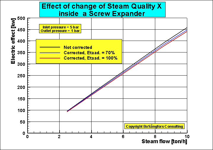
Fig.2
ŁŁŁŁŁŁŁŁŁŁŁŁŁŁŁŁŁŁŁŁŁŁŁŁŁŁŁŁŁŁŁŁŁŁŁŁŁŁŁŁŁŁŁŁŁŁŁŁŁŁŁŁŁŁŁŁŁŁŁŁŁŁŁŁŁŁŁŁŁŁŁŁŁŁŁŁŁŁŁŁŁŁŁŁŁŁŁŁŁŁŁŁŁŁŁŁŁŁŁŁŁŁŁŁŁŁŁŁŁŁŁŁŁŁŁŁŁŁŁŁŁŁŁŁŁŁŁŁŁŁŁŁŁŁŁŁŁŁŁŁŁ
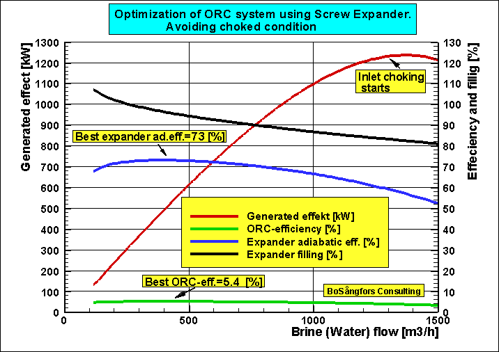
Avoiding inlet flow choking at a Screw Expander inlet
As can be seen it is very important to have a good design point.
Too high brine flow leads to inlet choking at 1350 m3/h.
The best ORC-efficiency is for this screw expander at 400 m3/h.
I.e ORC-eff. = 5.4 %
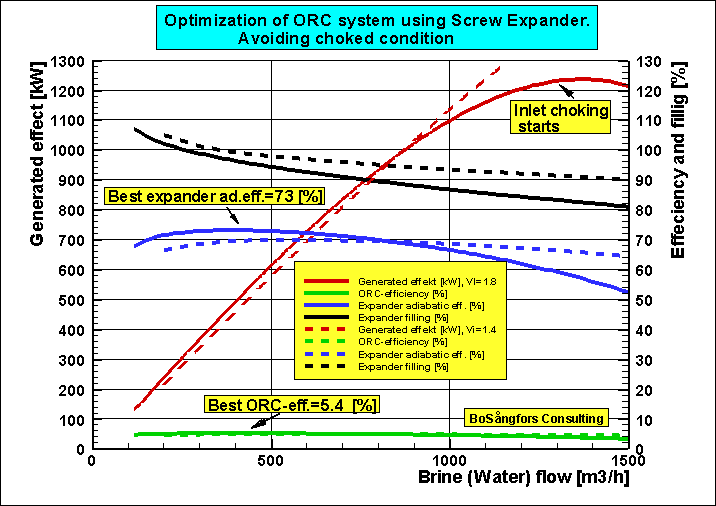
The graph below is the same as this above with the exception that data for Vi =1.4 are added for comparison with data from Vi=1.8
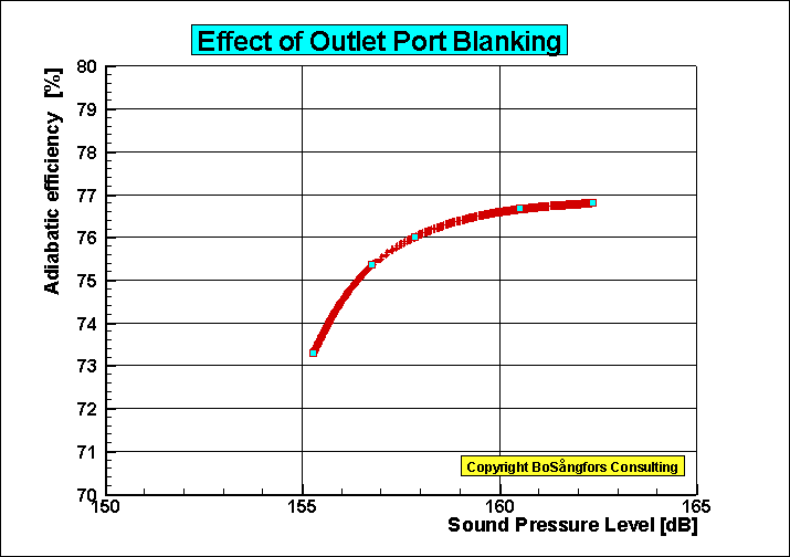
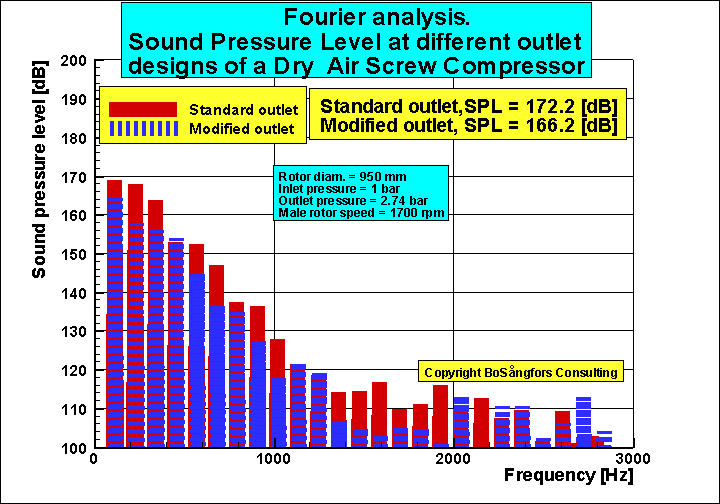
Influence of blanking upon SPL(Sound Pressure Level) of a Screw Compressor Outlet
Results from discussions with Elvedin Mujic, City University London.
![]()
![]()
In order to
give some information about the effect of different built-in volume ratio upon
the generation of noise from the outlet of a twin screw compressor these
calculations are presented.
![]()
The screw compressor is an oil injected refrigeration screw compressor.
Refrigerant = 134a
Rotor diameter =
162.7 mm
Oil injection rate = 66 lit/min
Male
rotor speed = 3000 rpm
Inlet:
Pressure = 2.006 bar
Temp. = 0
centigrade.
Corresponds
to -10 centigrade evaporation temp. and 10 centigrade superheat.
Outlet:
Pressure =
10.166
bar
Corresponds to 40 centigrade condensing
temp.
The
compressor has a pipe of inside diameter = 250 mm and length = 2000 mm mounted
to the compressor outlet.
The reported
point of sound pressure level SPL is located at the end of the 2000 mm pipe.
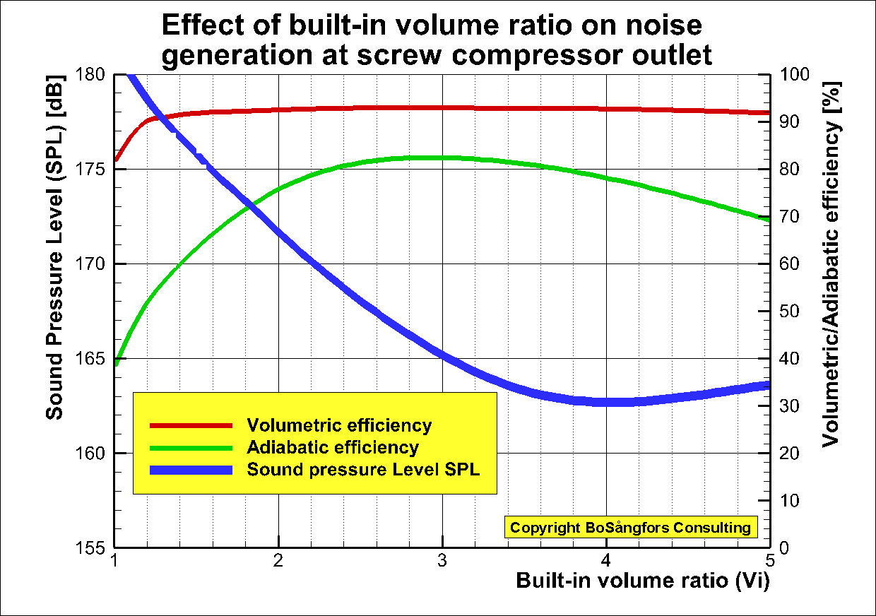
Fig. 1
As is shown in fig. 1 the built-in volume ratio Vi is very important for the adiabatic efficiency of a screw compressor, but also for the generation of noise.
It is obvious that the sound pressure level SPL can be very high especially at built-in volume ratio close to 1.
Another
point of interest is that the lowest
SPL is obtained at built-in volume ratio Vi
= 4
and not at 3,
which is the optimum value for adiabatic
efficiency.
A look at fig.2 can explain the presented effects.
As is shown the discharge starts with high backflow into the control volume since the opening pressure in the control volume is close to the filling pressure.
Then a
long discharge procedure starts.
At
Vi =
3
(optimum value) the discharge procedure is much shorter but still starts with a
small backflow.
At
Vi =
4 there is no backflow, which probably together
with a slight blanking effect explains
why the SPL is
lowest.
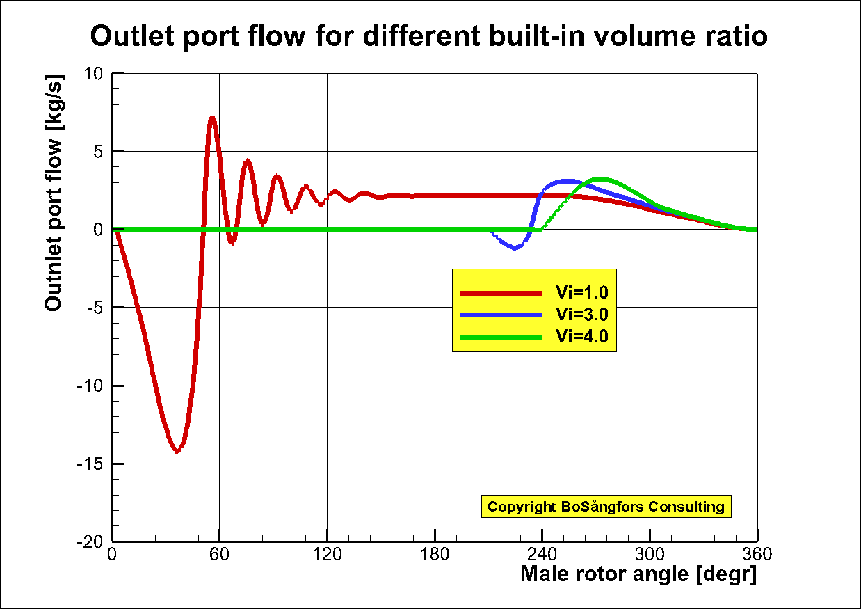
Fig. 2
Reference:
https://www.researchgate.net/publication/254636763_Modeling_Measurements_and_Analysis_of_Ga s-Flow_Generated_Noise_From_Twin-Screw_Compressors
ŁŁŁŁŁŁŁŁŁŁŁŁŁŁŁŁŁŁŁŁŁŁŁŁŁŁŁŁŁŁŁŁŁŁŁŁŁŁŁŁŁŁŁŁŁŁŁŁŁŁŁŁŁŁŁŁŁŁŁŁŁŁŁŁŁŁŁŁŁŁŁŁŁŁŁŁŁŁŁŁŁŁŁŁŁŁŁŁŁŁŁŁŁŁŁŁŁŁŁŁŁŁŁŁŁŁŁŁŁŁŁŁŁŁŁŁŁŁŁŁŁŁŁŁŁŁŁŁŁŁŁ
BoSÕngfors Consulting, Sweden
ŁŁŁŁŁŁŁŁŁŁŁŁŁŁŁŁŁŁŁŁŁŁŁŁŁŁŁŁŁŁŁŁŁŁŁŁŁŁŁŁŁŁŁŁŁŁŁŁŁŁŁŁŁŁŁŁŁŁŁŁŁŁŁŁŁŁŁŁŁŁŁŁŁŁŁŁŁŁŁŁŁŁŁŁŁŁŁŁŁŁŁŁŁŁŁŁŁŁŁŁŁŁŁŁŁŁŁŁŁŁŁŁŁŁŁŁŁŁŁŁŁŁŁŁŁŁŁŁŁŁŁŁŁŁŁŁŁŁŁŁŁŁŁŁŁŁŁŁŁŁŁŁŁŁ
BoSÕngfors Consulting, Sweden
Pressure
and gas/oil temperatures during, filling, compression and discharge of
a screw compressor
Input data:
Gas =Air
Pressure in = 1 bar
Pressure out = 8 bar
Temperature air in = 27 centigrade
Temperature Injected oil in = 60 centigrade
Built-in volume ratio = 4.42
Rotor diameter = 111 mm
Male rotor tip speed = 25 m/s
Closing of inlet port = 375 degr.
Injection of oil = 395 degr.
Opening of discharge port = 635 degr.
--------------------------------------------------------------
Calculated results
---------------------------------------------------------------------
Volumetric efficiency = 0.875
Adiabatic efficiency = 0.778
Outlet temperature = 74.1
---------------------------------------------------------------------------------------------------------------------------------
The computer simulations are performed with a modified version of the theory presented in the 1984 Purdue paper
ōComputer
Simulation of the Oil Injected Twin Screw Compressorö.
Input data:
Refrigerant =R134a
Pressure in = 2.928 bar
Pressure out = 10.17 bar
Temperature air in = 10.0 centigrade
Temperature Injected oil in = 40 centigrade
Built-in volume ratio = 2.7
Rotor diameter = 111 mm
Male rotor tip speed = 25 m/s
Closing of inlet port = 375 degr.
Injection of oil = 395 degr.
Opening of discharge port = 593 degr.
---------------------------------------------------------------
Calculated results
---------------------------------------------------------------------
Volumetric efficiency = 0.908
Adiabatic efficiency = 0.754
Outlet temperature = 48.7 centigrade
---------------------------------------------------------------------------------------------------------------------------------
The computer simulations are performed with a modified version of the theory presented in the 1984 Purdue paper
ōComputer
Simulation of the Oil Injected Twin Screw Compressorö.
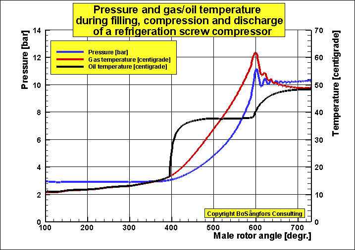
Fig. 2.
ŁŁŁŁŁŁŁŁŁŁŁŁŁŁŁŁŁŁŁŁŁŁŁŁŁŁŁŁŁŁŁŁŁŁŁŁŁŁŁŁŁŁŁŁŁŁŁŁŁŁŁŁŁŁŁŁŁŁŁŁŁŁŁŁŁŁŁŁŁŁŁŁŁŁŁŁŁŁŁŁŁŁŁŁŁŁŁŁŁŁŁŁŁŁŁŁŁŁŁŁŁŁŁŁŁŁŁŁŁŁŁŁŁŁŁŁŁŁŁŁŁŁŁŁŁŁŁŁŁŁŁŁŁŁŁŁŁŁŁŁŁŁ
BoSÕngfors Consulting, Sweden
Leakage analysis of a Twin Screw Compressor.
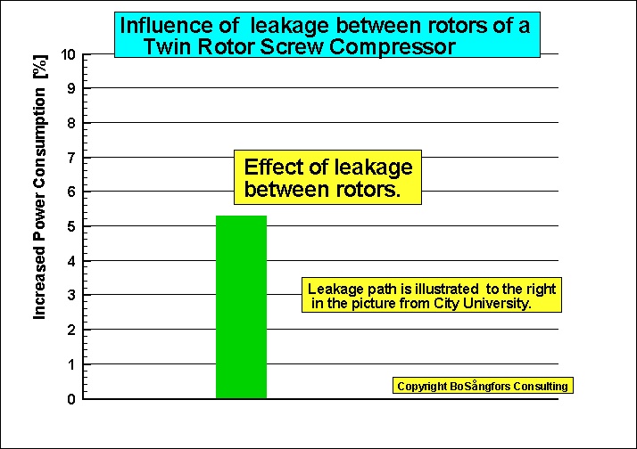
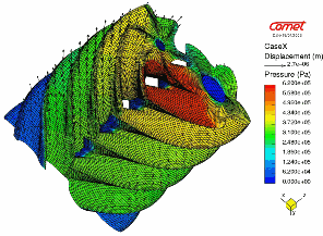
ŁŁŁŁŁŁŁŁŁŁŁŁŁŁŁŁŁŁŁŁŁŁŁŁŁŁŁŁŁŁŁŁŁŁŁŁŁŁŁŁŁŁŁŁŁŁŁŁŁŁŁŁŁŁŁŁŁŁŁŁŁŁŁŁŁŁŁŁŁŁŁŁŁŁŁŁŁŁŁŁŁŁŁŁŁŁŁŁŁŁŁŁŁŁŁŁŁŁŁŁŁŁŁŁŁŁŁŁŁŁŁŁŁŁŁŁŁŁŁŁŁŁŁŁŁŁŁŁŁŁŁŁŁŁŁŁŁŁŁŁŁŁŁŁŁŁŁŁŁŁŁŁŁŁ
BoSÕngfors Consulting, Sweden
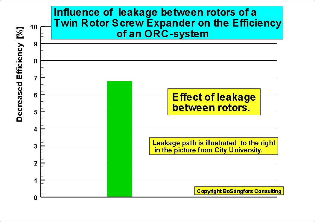
Leakage
analysis of a Twin Screw Expander.
ŁŁŁŁŁŁŁŁŁŁŁŁŁŁŁŁŁŁŁŁŁŁŁŁŁŁŁŁŁŁŁŁŁŁŁŁŁŁŁŁŁŁŁŁŁŁŁŁŁŁŁŁŁŁŁŁŁŁŁŁŁŁŁŁŁŁŁŁŁŁŁŁŁŁŁŁŁŁŁŁŁŁŁŁŁŁŁŁŁŁŁŁŁŁŁŁŁŁŁŁŁŁŁŁŁŁŁŁŁŁŁŁŁŁŁŁŁŁŁŁŁŁŁŁŁŁŁŁŁŁŁ
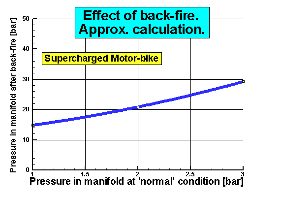
Edstroem Consulting, Sweden
Prediction of pressure in the manifold between Supercharger and Engine in the case of
back-fire.
ŁŁŁŁŁŁŁŁŁŁŁŁŁŁŁŁŁŁŁŁŁŁŁŁŁŁŁŁŁŁŁŁŁŁŁŁŁŁŁŁŁŁŁŁŁŁŁŁŁŁŁŁŁŁŁŁŁŁŁŁŁŁŁŁŁŁŁŁŁŁŁŁŁŁŁŁŁŁŁŁŁŁŁŁŁŁŁŁŁŁŁŁŁŁŁŁŁŁŁŁŁŁŁŁŁŁŁŁŁŁŁŁŁŁŁŁŁŁŁŁŁŁŁŁŁŁŁŁŁŁŁŁŁŁŁŁŁŁŁŁŁ
BoSÕngfors Consulting, Sweden
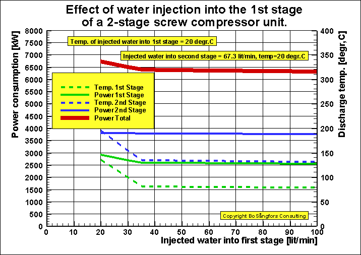
Effect of water injection into the first stage of a two-stage screw compressor unit
These computer simulations are using a modified theory of that described in the papers:
ōComputer Simulation of Effects from Injection of Different Liquids in Screw Compressorsö, Purdue 1998ō and
"Numerical calculation of effects from injection of different liquids in twin screw compressorsö, VDI 1998.
The results of the presented calculations show that at water injection rate 67.3 lit/min to the 2nd stage
and 37 lit/min to the 1st stage gives reduced power consumption.
Further increase of the 1st stage water injection rate does not improve the performance very much.
ŁŁŁŁŁŁŁŁŁŁŁŁŁŁŁŁŁŁŁŁŁŁŁŁŁŁŁŁŁŁŁŁŁŁŁŁŁŁŁŁŁŁŁŁŁŁŁŁŁŁŁŁŁŁŁŁŁŁŁŁŁŁŁŁŁŁŁŁŁŁŁŁŁŁŁŁŁŁŁŁŁŁŁŁŁŁŁŁŁŁŁŁŁŁŁŁŁŁŁŁŁŁŁŁŁŁŁŁŁŁŁŁŁŁŁŁŁŁŁŁŁŁŁŁŁŁŁŁŁŁŁŁŁŁŁŁŁŁŁŁŁŁŁŁŁŁŁŁŁŁŁŁŁŁŁŁŁŁŁŁŁŁŁŁŁŁŁŁŁŁŁŁŁŁŁ
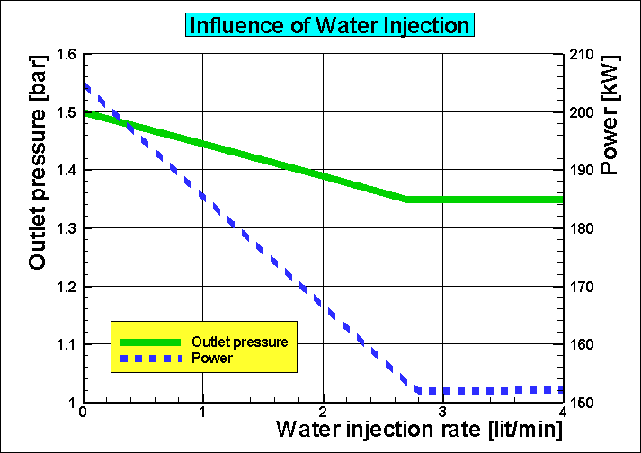
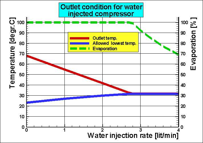
Influence of water injection on outlet parameters after a radial supercharger.
HEAT EXCHANGERS
ŁŁŁŁŁŁŁŁŁŁŁŁŁŁŁŁŁŁŁŁŁŁŁŁŁŁŁŁŁŁŁŁŁŁŁŁŁŁŁŁŁŁŁŁŁŁŁŁŁŁŁŁŁŁŁŁŁŁŁŁŁŁŁŁŁŁŁŁŁŁŁŁŁŁŁŁŁŁŁŁŁŁŁŁŁŁŁŁŁŁŁŁŁŁŁŁŁŁŁŁŁŁŁŁŁŁŁŁŁŁŁŁŁŁŁŁŁŁŁŁŁŁŁŁŁŁŁŁŁŁŁŁŁŁŁŁŁŁŁŁŁŁŁŁŁŁŁ
BoSÕngfors Consulting, Sweden
Calculated
Performance of a Rotary Heat Exchanger during start-up in a Power Plant
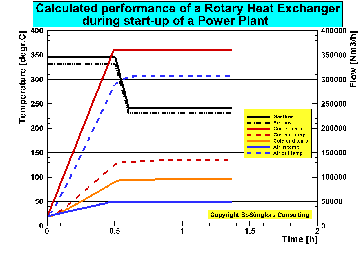
NOTE: When the flue gas contains for instance sulphuric acid it is necessary to start with high excess air. By doing that you get a smaller concentration of sulphuric acid in the flue gas and a lower condensation temperature. Then you avoid condensation deep into the heat transfer elements.
ŁŁŁŁŁŁŁŁŁŁŁŁŁŁŁŁŁŁŁŁŁŁŁŁŁŁŁŁŁŁŁŁŁŁŁŁŁŁŁŁŁŁŁŁŁŁŁŁŁŁŁŁŁŁŁŁŁŁŁŁŁŁŁŁŁŁŁŁŁŁŁŁŁŁŁŁŁŁŁŁŁŁŁŁŁŁŁŁŁŁŁŁŁŁŁŁŁŁŁŁŁŁŁŁŁŁŁŁŁŁŁŁŁŁŁŁŁŁŁŁŁŁŁŁŁŁŁŁŁŁŁŁŁŁŁŁŁŁŁŁŁŁŁŁŁŁŁ
BoSÕngfors Consulting, Sweden
Temperatures and Water content in Regenerative resp. Recuperative Heat Exchanger operating under water dew point.
Inlet condition = Flue gas with water spray injection.
Flue gas inlet temperature = Water dew point temperature
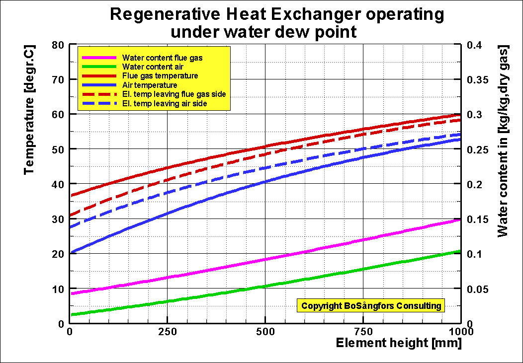
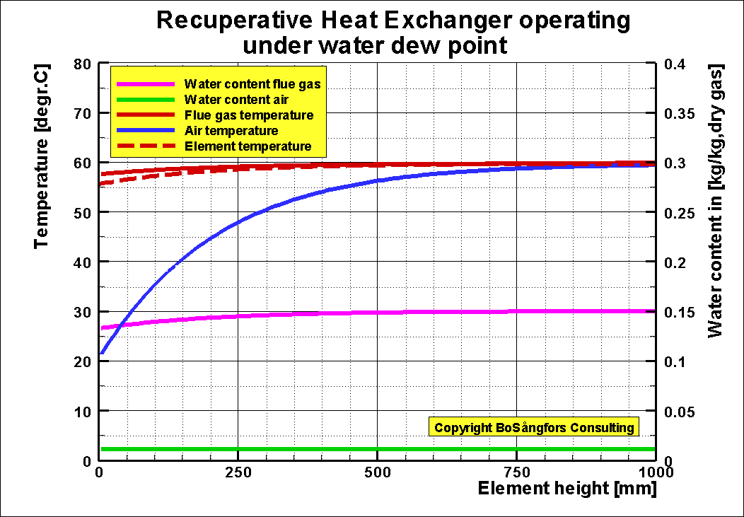
Please also look at: http://www.freepatentsonline.com/5482108.html
ŁŁŁŁŁŁŁŁŁŁŁŁŁŁŁŁŁŁŁŁŁŁŁŁŁŁŁŁŁŁŁŁŁŁŁŁŁŁŁŁŁŁŁŁŁŁŁŁŁŁŁŁŁŁŁŁŁŁŁŁŁŁŁŁŁŁŁŁŁŁŁŁŁŁŁŁŁŁŁŁŁŁŁŁŁŁŁŁŁŁŁŁŁŁŁŁŁŁŁŁŁŁŁŁŁŁŁŁŁŁŁŁŁŁŁŁŁŁŁŁŁŁŁŁŁŁŁŁŁŁŁŁŁŁŁŁŁŁŁŁŁŁ
BoSÕngfors Consulting, Sweden
Leakage analysis of a Tri-sector Rotary Heat Exchanger.
Rotor diameter = 8.283 m
Rotor height = 2.143 m
Rotor speed =
2 rpm
Element
porosity = 0.84
Flue gas flow = 454183 kg/h
Air sector primary = 30 degree.
Air sector secondary = 150 degree.
Gas sector = 180 degree.
PRESSURES [Pa]
Air in primary P1= 11442
Air out primary P2= 11234
Air in secondary P1s= 2179
Air out secondaryP2s= -79
Gas in P3= -497
Gas out P4 = -1942
CIRCUMFERENTIAL SEAL CLEARANCES [mm]
Primary in S1= 1
Primary out S2= 1
Secondary in S1s=1
Secondary outS2s=1
Gas in S3=1
Gas out S4=1
TEMPERATURES [degr.C]
Air in
primary T1=50
Air out
primary T2=372
Air in
secondary T1s=55
Air out
secondary T2s=357
Gas in T3=390
SECTOR PLATE
CLEARANCES [mm]
Cold end =2
Hot end =2
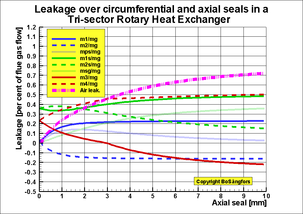
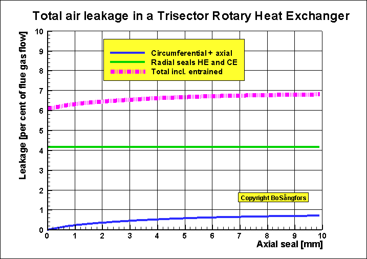
NOMENCLATURE (diagrams)
pma = pressure in volume between
casing and rotor, primary air [Pa]
pmas = pressure in volume between
casing and rotor, secondary air [Pa]
pmg = pressure in volume between
casing and rotor, gas [Pa]
m1 = flow over circumferential seal
primary inlet air [kg/h]
m2 = flow over circumferential seal
primary outlet air [kg/h]
mps = flow over axial seal from
primary to secondary [kg/h]
m1s = flow over circumferential seal
secondary to gas [kg/h]
m2s = flow over circumferential seal
secondary outlet air [kg/h]
msg= flow over axial seal from
primary to gas [kg/h]
m3 = flow over circumferential seal
inlet gas, [kg/h]
m4 = flow over circumferential seal
outlet gas, [kg/h]
mg = flue gas flow [kg/h]
Air leak = Air leakage into gas [per cent of flue gas mass flow]
BoSÕngfors Consulting, Sweden
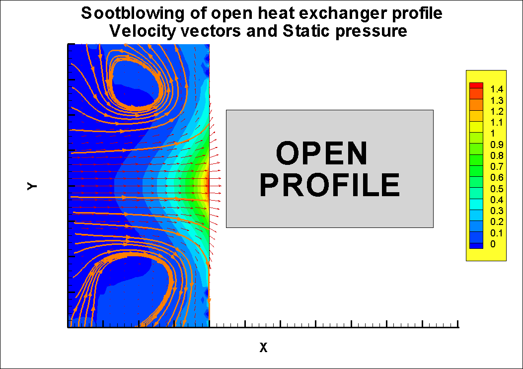
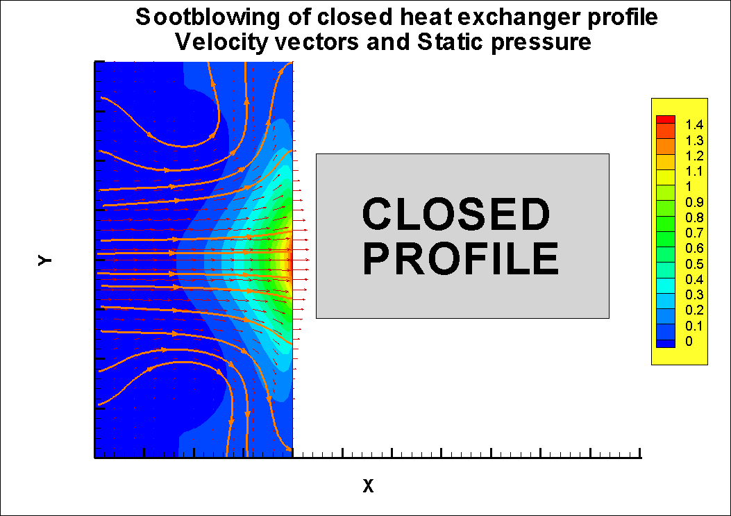
Sootblowing of open and closed element profiles for Heat Exchangers.
ŁŁŁŁŁŁŁŁŁŁŁŁŁŁŁŁŁŁŁŁŁŁŁŁŁŁŁŁŁŁŁŁŁŁŁŁŁŁŁŁŁŁŁŁŁŁŁŁŁŁŁŁŁŁŁŁŁŁŁŁŁŁŁŁŁŁŁŁŁŁŁŁŁŁŁŁŁŁŁŁŁŁŁŁŁŁŁŁŁŁŁŁŁŁŁŁŁŁŁŁŁŁŁŁŁŁŁŁŁŁŁŁŁŁŁŁŁŁŁŁŁŁŁŁŁŁŁŁŁŁŁŁŁŁŁŁŁŁŁŁŁŁŁŁŁŁŁ
BoSÕngfors Consulting, Sweden
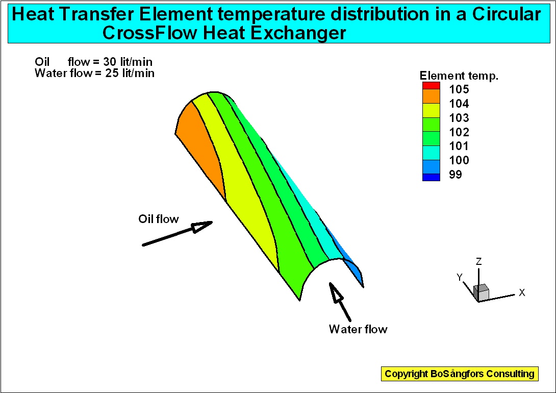
Calculation of Temperatures in a CrossFlowHeat Exchanger.

![]()
Bes÷kare totalt:
Bes÷kare denna mÕnad:
Bes÷kare denna vecka:
Bes÷kare idag:
http://docs.lib.purdue.edu/cgi/viewcontent.cgi?article=2442&context=iracc
Now I changed the second stage from Screw Expander to a R245faTurbine.
The performance is the same, but the turbine is a smaller machine than a Screw Expander.
.
The article: